
Rotor Cage To Transition Cone Interface For Agricultural Harvester

Active Publication Date: 2019-05-09
BLUE LEAF I P
View PDF9 Cites 0 Cited by
  • Summary
  • Abstract
  • Description
  • Claims
  • Application Information

AI Technical Summary

Benefits of technology

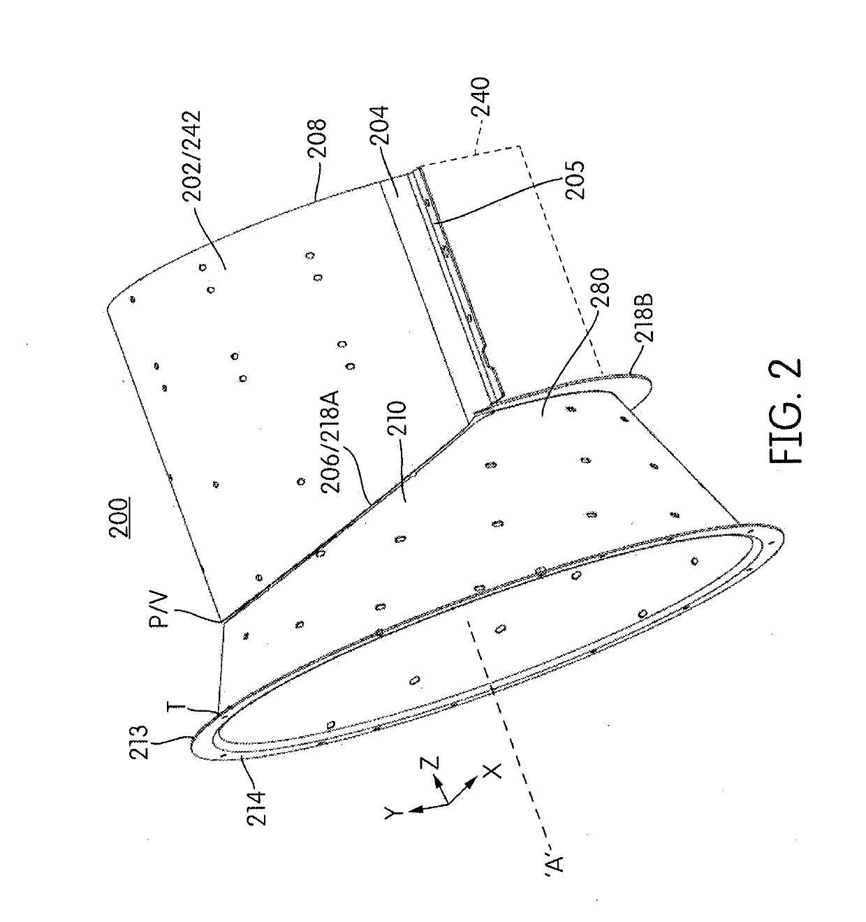
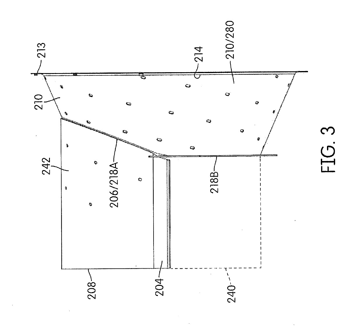
The invention is a threshing system for an agricultural harvester that includes a rotor cage, a threshing space between the rotor and the rotor, and a transition cone that leads into the rotor cage. The transition cone is positioned upstream of the rotor cage and its interface with the rotor cage is designed in a curved shape in three dimensions to maximize the threshing space. This results in a more efficient and effective threshing process.

Problems solved by technology

Simply enlarging the rotor cage is not necessarily possible in all harvesters due to vertical clearance limitations within the harvester.

Method used


Image

  • Rotor Cage To Transition Cone Interface For Agricultural Harvester
  • Rotor Cage To Transition Cone Interface For Agricultural Harvester
  • Rotor Cage To Transition Cone Interface For Agricultural Harvester

Examples


Embodiment Construction

[0019]Corresponding reference characters indicate corresponding parts throughout the several views. The exemplification set out herein illustrates an embodiment of the invention, in one form, and such exemplification is not to be construed as limiting the scope of the invention in any manner.

[0020]The terms “grain”, “straw” and “tailings” are used principally throughout this specification for convenience but it is to be understood that these terms are not intended to be limiting. “Grain” refers to that part of the crop material which is threshed and separated from the discardable part of the crop material, which is referred to as non-grain crop material, MOG or straw. Incompletely threshed crop material is referred to as “tailings”. Also the terms “forward”, “rearward”, “left” and “right”, when used in connection with the agricultural harvester and / or components thereof are usually determined with reference to the direction of forward operative travel of the harvester, but again, th...


PUM


Abstract

A threshing system of an agricultural harvester includes a rotor cage surrounding a rotor, a threshing space defined between the rotor cage and the rotor, and a transition cone defining an infeed to the rotor cage and the threshing system. A mating interface between the rotor cage and the transition cone is curved in three different dimensions of a Cartesian coordinate system for maximizing the threshing space. As viewed from above the mating interface of the threshing system, a convex portion of the rotor cage is mounted to a concave portion of the transition cone.

Description

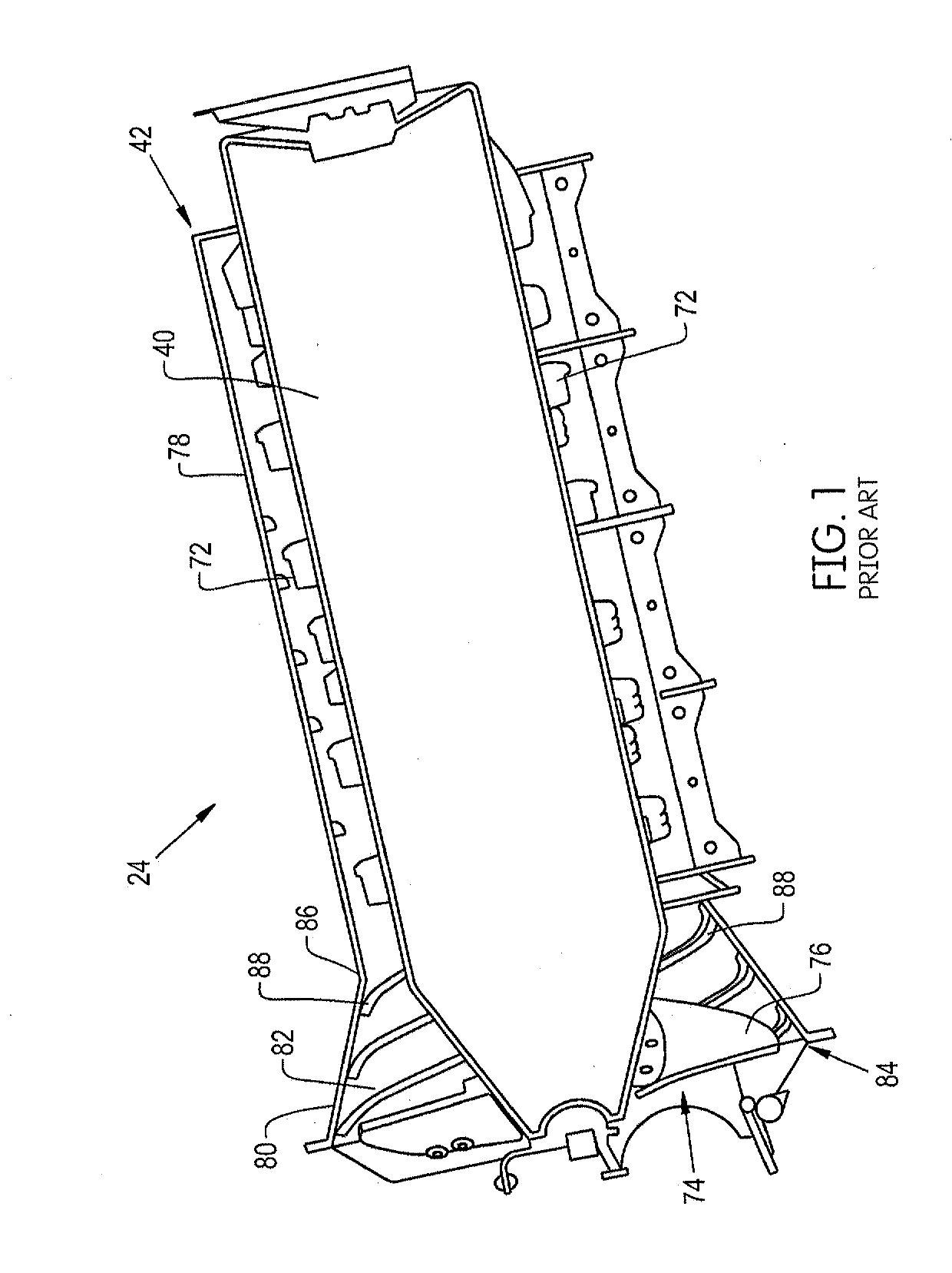
FIELD OF THE INVENTION[0001]The present invention relates to an interface between a rotor cage and a transition cone for a combine harvester.BACKGROUND OF THE INVENTION[0002]As is described in U.S. Patent Application No. 2017 / 0105350 to CNH America LLC, which is incorporated by reference in its entirety and for all purposes, a rotary threshing or separating system of an agricultural combine harvester includes one or more rotors which can extend axially (front to rear) or transversely (side to side) within the body of the combine, and which are partially or fully surrounded by a perforated concave. The crop material is threshed and separated by the rotation of the rotor within the concave. Coarser non-grain crop material such as stalks and leaves are transported to the rear of the combine and discharged back to the field. The separated grain, together with some finer non-grain crop material such as chaff, dust, straw, and other crop residue are discharged through the concaves and fal...

Claims


Application Information

Patent Timeline
IPC IPC(8): A01F7/06
CPCA01F7/062A01F12/46A01F7/067
Inventor FLICKINGER, WAYNEKEMMERER, BENJAMIN
Owner BLUE LEAF I P
Learn More