
Roadway Barrier

a technology for roads and barriers, applied in roads, pasturing equipment, road signs, etc., can solve the problems of reducing the service life of the reflector, affecting the service life of the road, and affecting the safety of the road,

Inactive Publication Date: 2016-06-16
PIENAAR SIMONE
View PDF0 Cites 2 Cited by
  • Summary
  • Abstract
  • Description
  • Claims
  • Application Information

AI Technical Summary

Benefits of technology

The invention relates to an improved design for securing connectors on a reflector shaft for lighting fixtures. A washer is used which can rotate around the shaft to create tension between the parts and make the panels' arms spread out. This helps ensure better stability and secure mounting of the components.

Problems solved by technology

The technical problem addressed by this patent is how to improve the design of roadway barriers made up of rails and reflectors, ensuring they are more efficient and easy to install while also optimizing the use of space along the guidewire.

Method used


Image

  • Roadway Barrier
  • Roadway Barrier
  • Roadway Barrier

Examples


Embodiment Construction

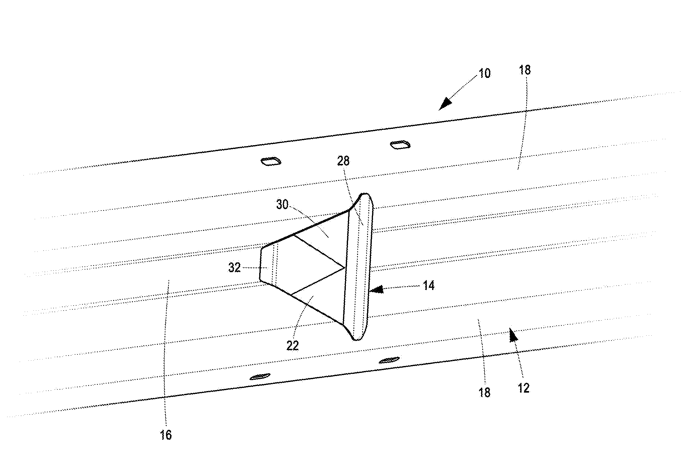
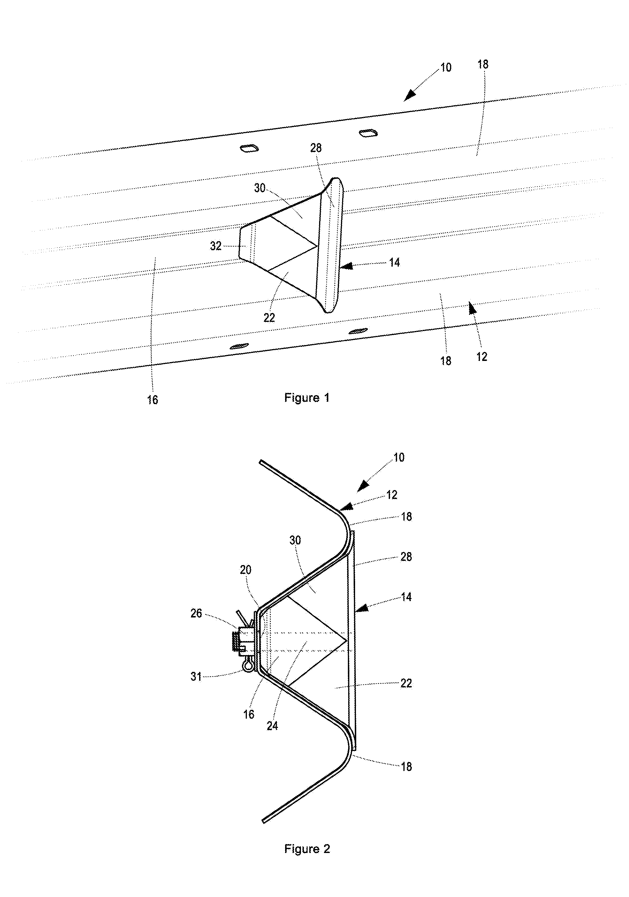
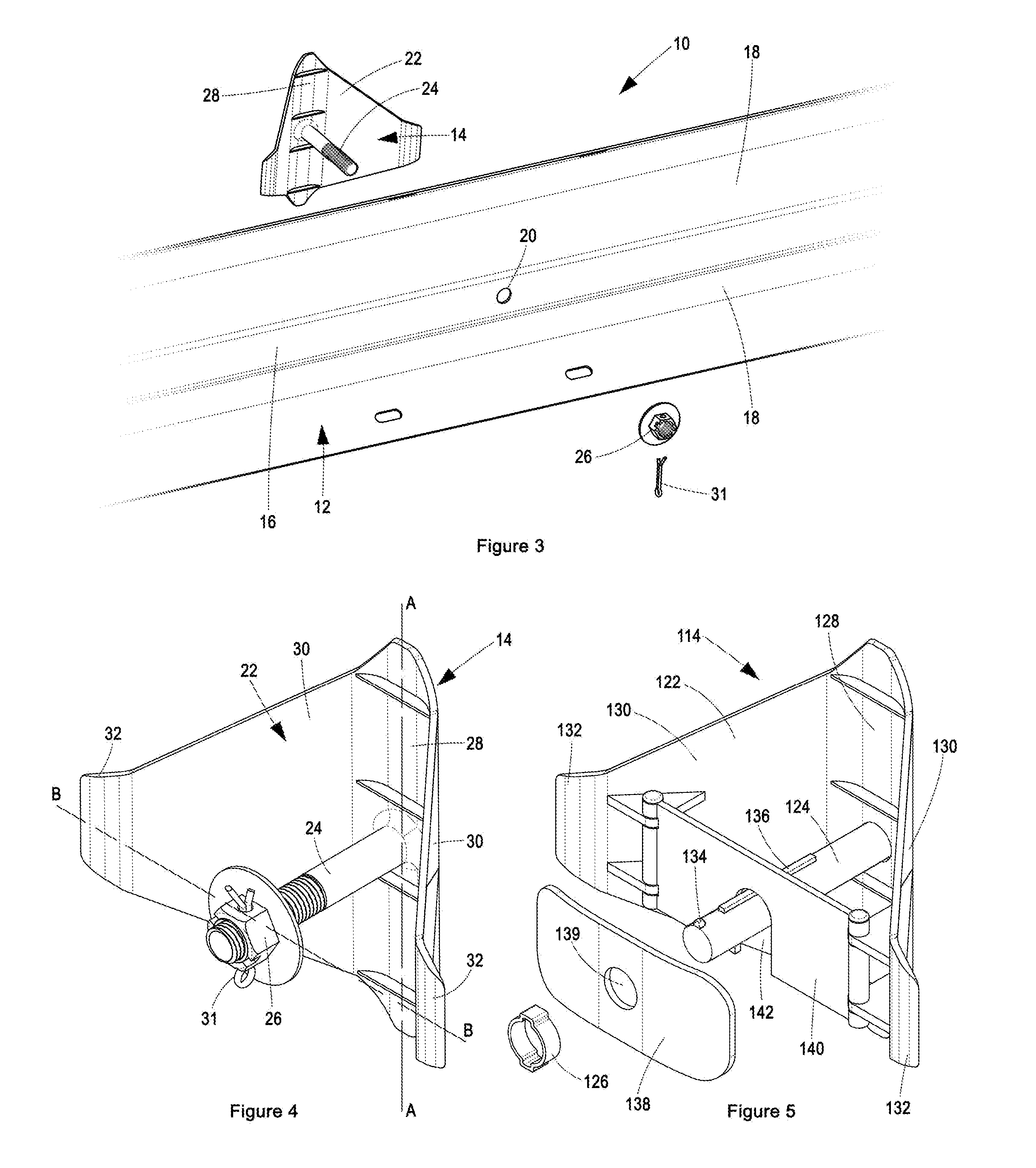
[0038]With reference to FIGS. 1 to 4, according to a preferred embodiment of the invention a roadway barrier 10 includes a rail 12 and a reflector 14.

[0039]The rail 12 is a standard guardrail suitable for use along roadsides. An example of such a guardrail is an Armco™ barrier. Referring specifically to FIGS. 2 and 3, the rail 12 is longitudinally corrugated, defining a longitudinal trough 16 between longitudinal ridges 18. Turning specifically to FIG. 3, the rail 12, in the region of the longitudinal trough 16, defines an aperture 20.

[0040]Turning to FIG. 4, the reflector 14 is sized and shaped to fit within the longitudinal trough 16 of the rail 12. The reflector 14 includes a panel 22, a shaft 24 and a connector 26.

[0041]The panel 22 is in shape substantially a rhombus, defining minor and major diagonals A-A and B-B, respectively (shown in FIG. 4). The panel 22 is bent / curved along its minor diagonal A-A substantially into a V-shape. The panel 22 in the region of the minor diagon...


PUM


Abstract

A roadway barrier includes: (i) a longitudinally corrugated rail defining a longitudinal trough between longitudinal ridges, which rail in the region of the trough, defines an aperture: (ii) a reflector comprising: (a) a substantially V-shaped panel with a reflective surface, the panel defining a spine and a pair of arms that diverge from the spine, and the panel arms being resiliently movable between a neutral condition and a splayed condition; (b) a shaft extending from the spine of the panel, between the panel arms, wherein each panel arm is substantially planar and tapers in height from the spine towards its free end; and (c) a connector for securing to the reflector shaft. The reflector is located within the trough defined by the rail, with the reflector shaft extending through the aperture defined by the rail and secured in place by the connector, which connector induces tension within the reflector shaft, with the panel arms bearing against the rail, in the region of the trough, and maintaining the panel arms in the splayed condition.

Description


Claims


Application Information

Patent Timeline
Owner PIENAAR SIMONE
Learn More