Light emitting device with tension relaxation

a technology of light emitting device and relaxation device, which is applied in the direction of glass pressing apparatus, glass making apparatus, manufacturing tools, etc., can solve problems such as package breakage, and achieve the effect of compromising the function of the devi

Active Publication Date: 2011-10-25
LUMILEDS
View PDF14 Cites 2 Cited by
  • Summary
  • Abstract
  • Description
  • Claims
  • Application Information

AI Technical Summary

Benefits of technology

[0013]When applied as a bonding material between LED-chips and optical elements, there is the additional effect that the material exhibits good properties as a bonding material for obtaining a physical and an optical bond between the LED-chip and the optical element, and is capable of relaxing thermally induced tension, therefore making it very suitable as a bonding material between LED chips and optical elements arranged directly on the LED chips.
[0017]In preferred embodiments, the optical element is of an inorganic material. To fully take advantage of the proposed bonding material, it is advantageous that the optical element is photo- and thermally stable, so that the light emitted by and the heat dissipated from the light emitting diode does not act deteriorating on the optical element, thereby compromising the function of the device. Inorganic materials, such as polycrystalline ceramic materials and certain glass materials, are among the materials having the desired properties.

Problems solved by technology

During operation of the LED, the temperature of the LED-package will gradually increase from ambient to a working temperature, at which the differences in coefficient of thermal expansion between the LED chip and the optical element could lead to break-down of the package.

Method used


Image

  • Light emitting device with tension relaxation
  • Light emitting device with tension relaxation

Examples


Embodiment Construction

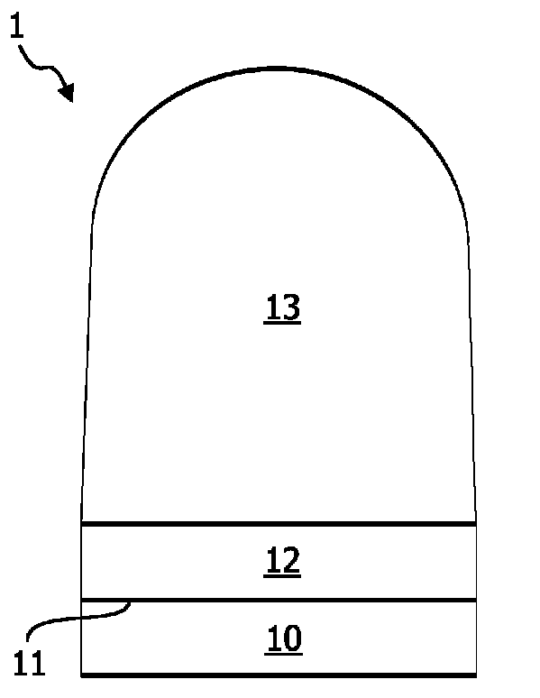
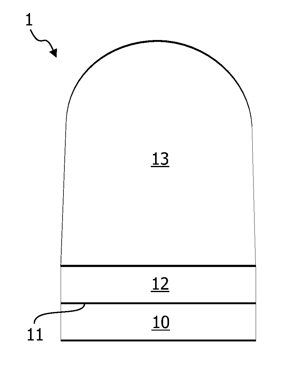
[0023]The present invention relates, in one aspect, to a light emitting device comprising a LED-chip and an optical element bound to a light emitting surface of said LED chip by means of a bonding material based on the use of glass materials having a glass transition temperature below the operating temperature of the LED-package.

[0024]One embodiment of such a light-emitting device 1, as illustrated in FIG. 1, comprises a light emitting diode (LED) 10 having a light-emitting surface 11, i.e. a surface through which light produced exits the LED.

[0025]An optical element 13 is arranged on the light-emitting surface 11 of the LED 10, and is bound thereto by means of a bond 12 comprising a bonding material.

[0026]The bonding material is mainly constituted by a glass material having a glass transition temperature (Tg) of up to 250° C.

[0027]The location of the bonding material is not limited to only be arranged on the light emitting surface of the LED, but may also be located on other interf...


PUM

PropertyMeasurementUnit
Tgaaaaaaaaaa
temperaturesaaaaaaaaaa
glass transition temperature Tgaaaaaaaaaa

Abstract

A light emitting device is provided, comprising a light emitting diode 10, where the light emitting surface 11 thereof is bound to an optical element 13 by means of a bonding material 12 comprising a phosphate glass or an oxide glass having Tg<250° C. In operation of the device, when the temperature approaches or exceeds Tg of the bonding material, the bonding material gets fluidic and can thus relax any thermally induced stresses between the light emitting diode and the optical element.

Description

[0001]This application is a national stage application under 35 U.S.C. §371 of International Application No. PCT / IB2007 / 053765 filed on Sep. 18, 2007, and published in the English language on Mar. 27, 2008 as International Publication No. WO / 2008 / 035283, which claims priority to European Application No. 06121092.8, filed on Sep. 22, 2006, incorporated herein by reference.FIELD OF THE INVENTION[0002]A light-emitting device comprising at least one light emitting diode and at least one optical element bonded to a light-emitting surface of said at least one light emitting diode by means of a bonding material.BACKGROUND OF THE INVENTION[0003]Light emitting diodes (LEDs) are currently contemplated as light sources for several different lighting applications, and the use of light emitting diodes is expected to grow in the coming years.[0004]A light emitting diode is typically comprised in a package containing the actual LED-chip comprising the active, light producing, layers, and light ext...

Claims


Application Information

Patent Timeline
Patent Type & Authority Patents(United States)
IPC IPC(8): H01L33/00C03B11/08C03B23/22C03C27/00C03C29/00H01L21/00H01L33/58
CPCH01L33/58H01L2924/0002H01L2924/00C03C3/16C03C3/122C03C8/24C03C27/00
Inventor OFFERMANS, PAULUS H. G.BECKERS, LUCAS J. A. M.
Owner LUMILEDS
Why Eureka
Try Eureka