
Systems and methods for an improved ratcheting device including pivoting tooth

Active Publication Date: 2022-05-12
NITE IZE
View PDF0 Cites 1 Cited by
  • Summary
  • Abstract
  • Description
  • Claims
  • Application Information

AI Technical Summary

Benefits of technology

The patent describes a ratchet device that can induce and release tension in webbing without the limitations of current ratchet devices. The ratchet device includes a ratchet wheel and two levers that are interconnected with the ratchet wheel. The device also includes a first pivoting bracket and a second pivoting bracket, which can hold a flat strap securely. The ratchet device can be used in various applications, such as tensioning straps and hooks. The technical effects of this invention include improved tensioning capabilities, new strain configurations, and improved strain release mechanisms.

Problems solved by technology

These ratchet designs as such, implemented in various guises and in a multitude of shapes and sizes, suffers several maladies.
Issues include that releasing tension from the straps held by the device can be frustratingly difficult, the performance of the device can degrade significantly over time, and the configurability of the device is limited.
Furthermore, the size and weight of the device can become a liability, particularly for those devices that incorporate permanently attached hooks.
However, after repeated use or use near the rated working load limit, the components of most ratchet devices begin to wear and / or deform such that removal of the webbing from the device becomes increasing frustrating to make happen.
In close confines with a surrounding structure, such as the bed area of a truck, the locked lever can impede rather than enhance removal of the webbing from the ratchet device.
Additionally, as the lever rotates toward the position for tension release, even though the eccentric is pushing the chassis sliding bracket towards the release point, the force applied to rotate the lever end eccentric is compromised due to the poor mechanical advantage afforded the lever.
Both methods are commonly used and both methods can pose a safety risk to the operator of the device.
This contact area experiences a high level of localized stress within the device.
Inspection of well used current art ratchet devices, particularly those that utilize die-cast levers will show excessive wear and / or deformation at these locations of the device.
Over time, the cumulative effect of these deformations will permanently alter the ratchet device.
The amount of travel induced in the chassis sliding bracket by the eccentric shape on the lever ends may no longer be sufficient to move the sliding bracket far enough to disengage the sliding bracket from the ratchet wheel teeth.
This failure mode occurs in ratchet devices that utilize sliding brackets to actuate the ratcheting action.
For the most part however, these devices remain essentially the same, as does the failure behavior.
The width requirements previously noted, in combination with the added burden to provide sufficient clearance around webbing configured in the device, precludes introducing blade stiffening geometries where they would help in preventing blade end deformation at higher force loads.
The possibility for both side-to-side translational movement and in-plane rotational movement of the sliding brackets creates another crippling disadvantage for current art ratchet devices.
In either case, both ratchet wheels are no longer fully engaged.
Despite creating an unsafe condition, the imbalance in load sharing can easily deform the blade portion of the sliding bracket where it engages the ratchet wheel tooth.
Subsequent use of the device is made difficult by the now deformed blade on the sliding bracket.
Another source for this misalignment, particularly in lower quality, lower load rated devices, is the chassis itself will twist about its long axis while tension is being ratcheted into the webbing.
This behavior, analogous to the wringing of water from a wet towel, will result in the chassis sliding bracket landing in an imbalanced load sharing position with respect to the ratchet wheel teeth.
However, if the embossments are located too close to the chassis and lever sidewalls, the sliding brackets will bind, not close enough and the sliding brackets rotate out of parallel as described above.
This is a design limitation of the sidewall slot / sliding bracket interaction of current art ratchet devices and is a source of frustration to those who use such devices.
However, the blade ends of the harder sliding bracket material tend to gull and / or scrape away the softer die-cast material on the lever eccentric located at the end of the lever.
Repeated use at or near working load limits will compromise and eventually break the die-cast eccentric surface, disabling the device and preventing release of the ratcheted tension.
In this condition, the means available to release tension from the webbing is to either cut the webbing or force release of the chassis sliding bracket using a supplementary tool, often a dangerous proposition.
Finally, when the compete configuration—device, straps, hooks (FIG. 35 Prior Art)—is taken into consideration, additional disadvantages arise that limit the overall effectiveness of the current art of ratchet devices.
Such an arrangement limits where the ratchet device can be positioned.
Often less than ideal access is afforded the user either in tensioning or in releasing tension from the ratchet device.
Additionally, ratchet devices with permanently attached straps and hooks can be heavy, requiring special care to prevent damage to surrounding objects when initially configuring the ratchet device, straps, and hooks.

Method used


Image

  • Systems and methods for an improved ratcheting device including pivoting tooth
  • Systems and methods for an improved ratcheting device including pivoting tooth
  • Systems and methods for an improved ratcheting device including pivoting tooth

Examples


first embodiment

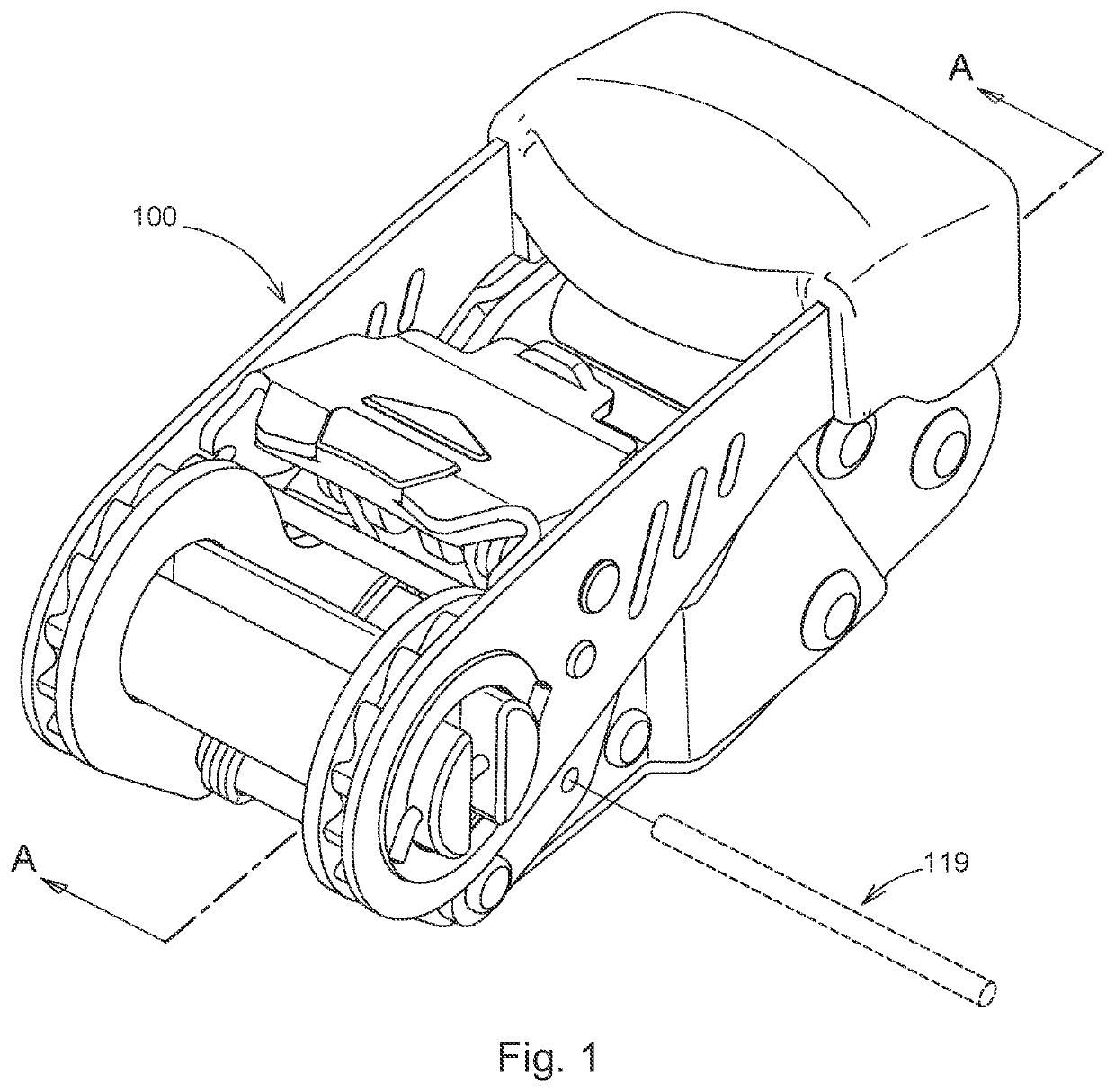
[0241]FIG. 23a through FIG. 23h show a sequence of isometric views depicting a step-wise progression for securing Enhanced Ratchet 100 to a short strap containing a sewn end-loop secured to an anchor location, and subsequently forming a fixed-end configuration between two anchor locations using a second length of webbing containing a permanently affixed hook. The short strap can be sized to an appropriate length best suited to the application. Enhanced Ratchet 100 can be attached to the short strap at any location along the strap. Note, the use of a removably attached strap enables the strap and first embodiment combination to be secured to a variety of anchor locations that otherwise could prove unsuitable for a sewn-on strap containing a sewn-on hook. This type of connection is referred to as a tethered anchor.

[0242]FIG. 24a through FIG. 24h show the same sequence from FIG. 23 with the short strap being removably secured to a hook. The configuration shown replicates the configurat...

embodiment 100

[0244]FIG. 26a through FIG. 26h show a sequence of isometric views depicting a step-wise progression for securing Enhanced Ratchet 100 to a length of webbing containing a sewn end-loop and two removably affixed S-hooks, subsequently anchored between two fixed positions forming a fixed-end configuration. The sequence shown is similar to the sequence depicted in FIG. 24, the difference being, instead of two straps, a single strap is used. The induced stress in the ratchet portion of the embodiment 100 is comparable to that of a current art device, yet the magnitude of the reaction force at the anchor locations is effectively doubled (FIG. 17d, FIG. 35d Prior Art). This represents a significant advantage over the current art.

[0245]FIG. 27a through FIG. 27e show a sequence of isometric views depicting a step-wise progression for securing Enhanced Ratchet 100 to a strap containing a sewn end-loop. Before the strap is secured to Enhanced Ratchet, the end containing a sewn end-loop is rout...

embodiment 380

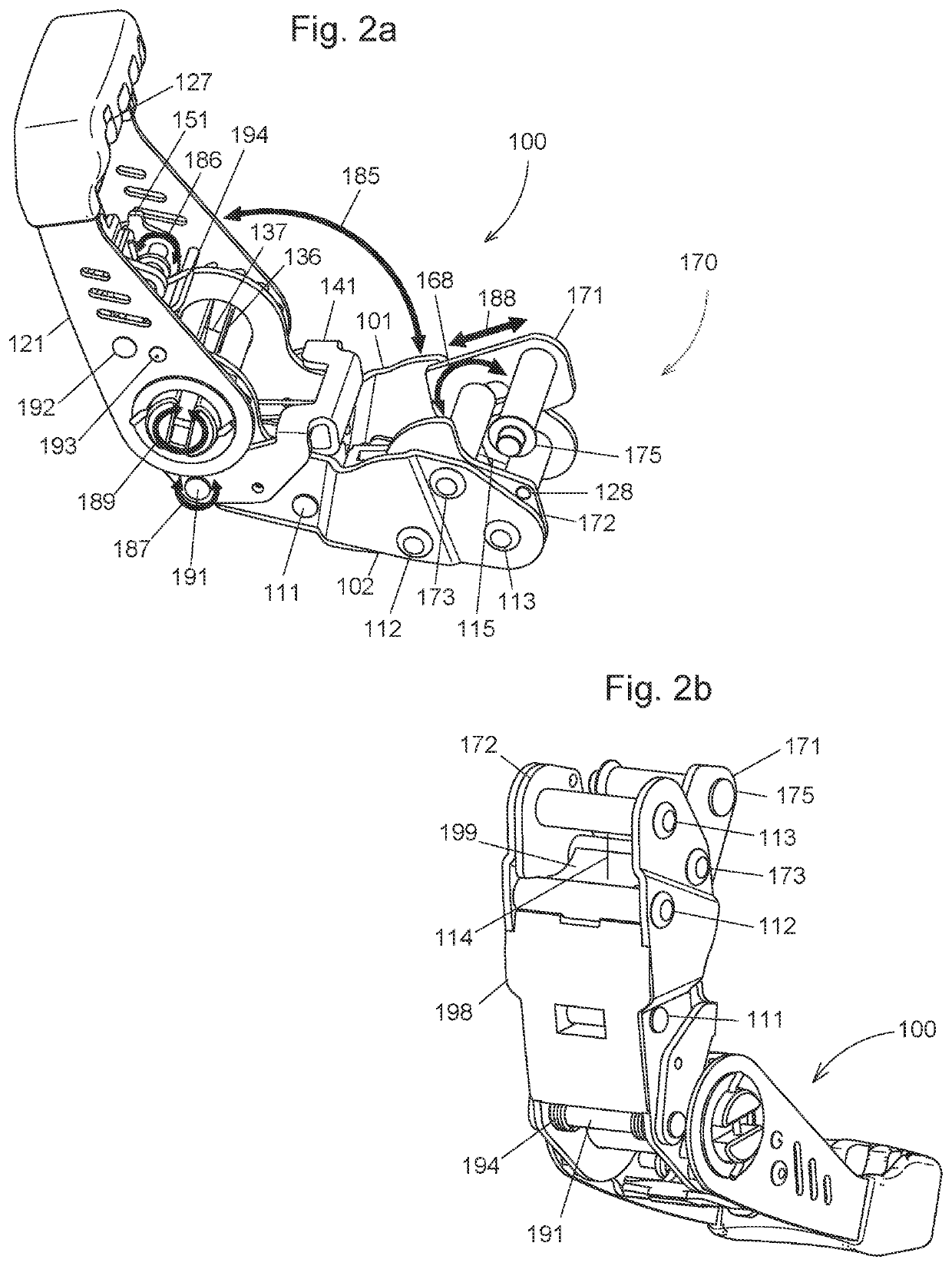
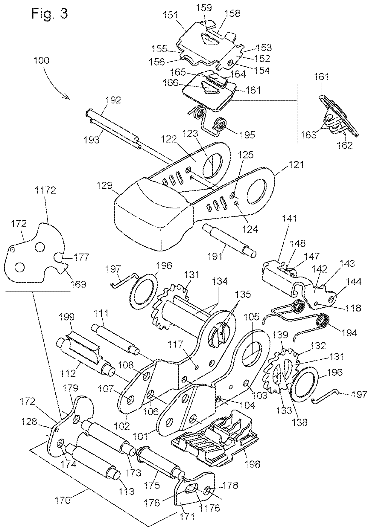
[0329]The embodiment 380 as shown in FIG. 33 and FIG. 34 incorporates the capture-frame assembly 170 into a cam-lock style webbing tensioning device. While not specifically a ratchet device, the embodiment is a tensioning device and shows how a typical cam-lock device could be improved by means of the capture-frame assembly.

[0330]In some embodiments of the capture frame assembly 170, the device may be used in an alternative configuration not with a ratchet, or with a more traditional ratchet. The capture frame assembly 170 is usable in a variety of contexts.

[0331]Although embodiments of the Enhanced Ratchet are in many contexts deployed in the context of webbing flat straps, the principles and designing of the ratcheting lever arms and rotating brackets may deployed in a variety of contexts not including flat straps. Additionally, in some contexts, the rotational mating of the brackets in order to release tension on the flat straps need not be enabled and a user may be required to p...


PUM


Abstract

A ratchet device includes a ratchet wheel. The ratchet device further includes a first lever, the first lever rotatably interconnected with the ratchet wheel. The ratchet device further includes a second lever, the second lever rotatably interconnected with the ratchet wheel. The ratchet device further includes a first pivoting bracket, the first pivoting bracket pivotally interconnected with the first lever. The ratchet device further includes a second pivoting bracket, the second pivoting bracket pivotally interconnected with the second lever. The first pivoting bracket has a first position where the first pivoting bracket is rotated to engage the ratchet wheel and a second position where the first pivoting bracket is rotated to disengage from the ratchet wheel.

Description

BACKGROUND[0001]Many devices that are designed to secure straps and to induce tension in straps exist today. Current art in strap tensioning ratchet devices reveals that a large portion of these devices utilize a singular design. These ratchet designs as such, implemented in various guises and in a multitude of shapes and sizes, suffers several maladies. Issues include that releasing tension from the straps held by the device can be frustratingly difficult, the performance of the device can degrade significantly over time, and the configurability of the device is limited. Furthermore, the size and weight of the device can become a liability, particularly for those devices that incorporate permanently attached hooks.[0002]As shown in FIG. 35 Prior Art and FIG. 36 Prior Art, a typical prior art ratchet device 400 is comprised of a chassis 402 and a rotating lever 404, each having a sliding bracket 412, 414, where the sliding brackets simultaneously engage a pair of ratchet wheels 406,...

Claims


Application Information

Patent Timeline
IPC IPC(8): A44B11/06
CPCA44B11/065B60P7/083F16D41/00Y10T24/2121Y10T24/2175B23P19/04
Inventor SEADER, REX
Owner NITE IZE
Learn More