
Spindle motor and disk drive apparatus

a technology of spindle motor and disk drive, which is applied in the direction of windings, instruments, record information storage, etc., can solve the problems of lead wire breaking, wire damage, and unwanted biting of passage lines, so as to minimize the passage lines of conducting wires

Inactive Publication Date: 2016-06-30
NIDEC CORP
View PDF0 Cites 3 Cited by
  • Summary
  • Abstract
  • Description
  • Claims
  • Application Information

AI Technical Summary

Benefits of technology

The invention reduces movement of the lead wires and passage lines of the conducting wires, which helps maintain the stability of the system.

Problems solved by technology

If a contact between the lead wire and the rotating member occurs, the lead wire may be damaged, and even a breaking of the lead wire may occur.
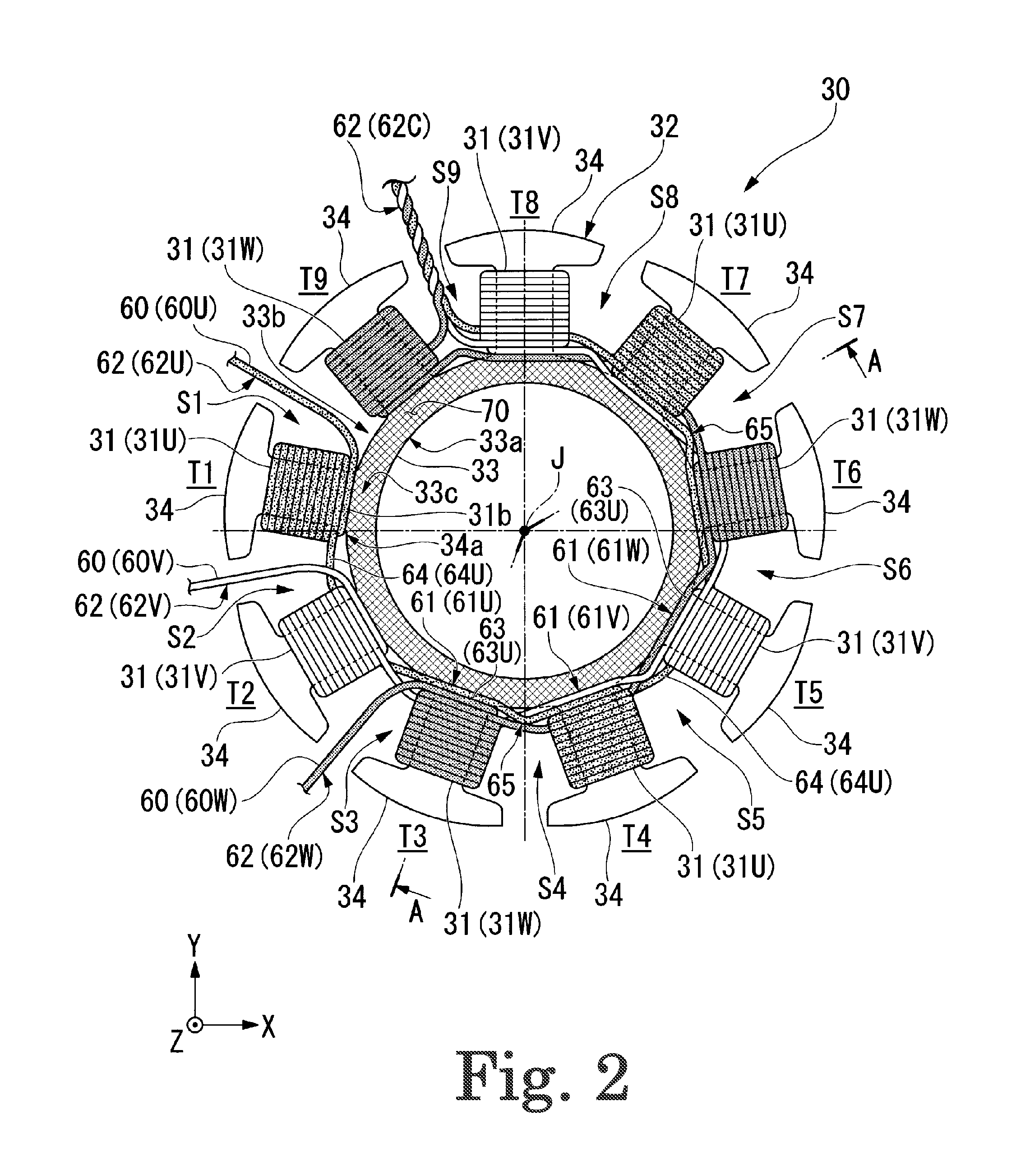
If the passage line lies on an inner portion of the core back, an unwanted biting of the passage line may occur when the stator core assembly is joined to the stationary member.

Method used


Image

  • Spindle motor and disk drive apparatus
  • Spindle motor and disk drive apparatus
  • Spindle motor and disk drive apparatus

Examples


Embodiment Construction

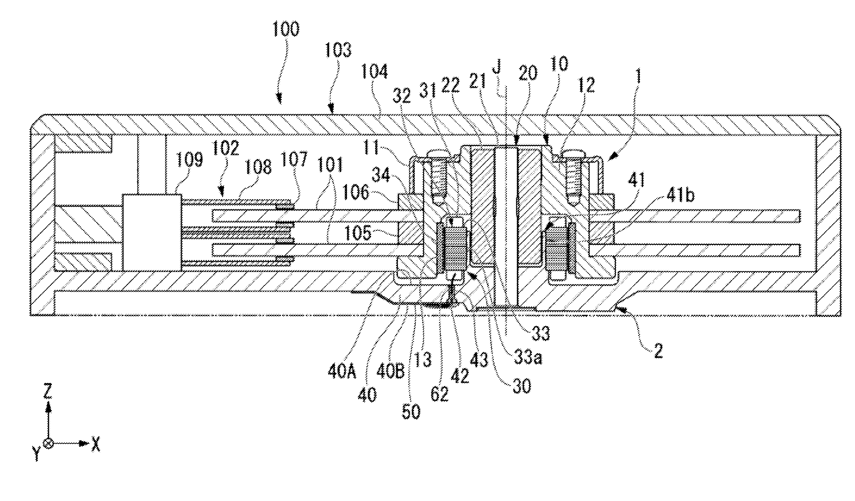
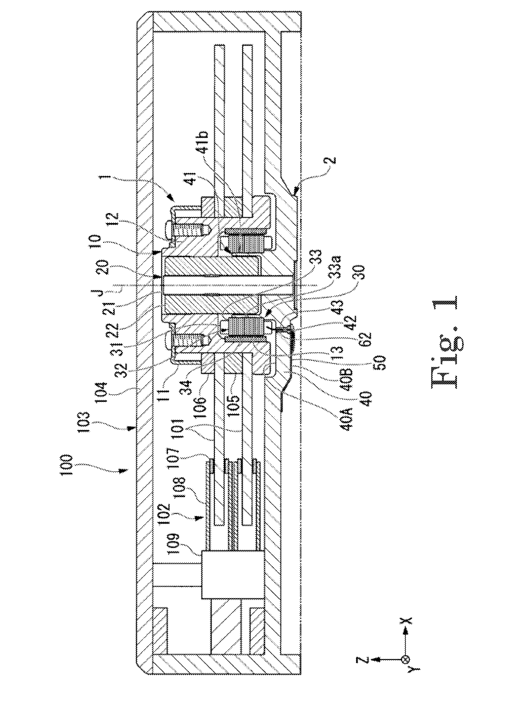
[0017]Hereinafter, preferred embodiments of the present invention will be described with reference to the accompanying drawings. Note that the scope of the present invention is not limited to the preferred embodiments described below, but includes any modification thereof within the scope of the technical idea of the present invention. Also note that scales, numbers, and so on of members or portions illustrated in the following drawings may differ from those of actual members or portions, for the sake of easier understanding of the members or portions.

[0018]In the following drawings, an xyz coordinate system is shown appropriately as a three-dimensional orthogonal coordinate system. In the xyz coordinate system, a z-axis direction is assumed to be a direction parallel to a central axis J extending in a vertical direction in FIG. 1. A y-axis direction is assumed to be a direction perpendicular to a z-axis. An x-axis direction is assumed to be a direction perpendicular to both the z-a...


PUM

PropertyMeasurementUnit
conductingaaaaaaaaaa
surfaceaaaaaaaaaa
insulatingaaaaaaaaaa

Abstract

A spindle motor includes a stationary portion and a rotating portion arranged to rotate about a central axis extending in a vertical direction with respect to the stationary portion. The stationary portion includes a stator portion including a stator core including an annular core back and a plurality of tooth portions arranged to extend radially outward from the core back, and coils wound around the plurality of tooth portions; an outside surface press fitted to an inside surface of the core back; and a fixing member arranged at least on an upper surface of the core back. Conducting wires defining the coils include passage lines each of which is arranged to join different ones of the coils to each other; and lead wires each of which is drawn out from one of the coils, and is drawn out from an upper side of upper surfaces of the tooth portions to a lower side of lower surfaces of the tooth portions. Each of the passage lines and the lead wires is arranged radially outward of the inside surface of the core back. The fixing member is arranged to fix at least a portion of each passage line and at least a portion of each lead wire to the stator core.

Description

BACKGROUND OF THE INVENTION[0001]1. Field of the Invention[0002]The present invention relates to a spindle motor and a disk drive apparatus.[0003]2. Description of the Related Art[0004]A disk drive apparatus, such as, for example, a hard disk drive, includes a spindle motor arranged to rotate a recording disk. A stator core assembly described in JP-A 2012-165628 includes a core back joined to a stationary member, and at least one tooth portion arranged to project from the core back and around which a conducting wire is wound. A passage line of the conducting wire is arranged on the core back. After the conducting wire is wound around the tooth portion, a lead wire, which is an end portion of the conducting wire, is arranged to pass axially below the tooth portion.[0005]The conducting wire described in JP-A 2012-165628 is wound in a counterclockwise direction around the tooth portion a plurality of times. Thereafter, the lead wire is drawn out axially downwardly of the tooth portion....

Claims


Application Information

Patent Timeline
Patent Type & Authority Applications(United States)
IPC IPC(8): H02K3/28G11B19/20H02K7/08
CPCH02K3/28G11B19/2009H02K7/086H02K3/522H02K2203/06G11B17/02
Inventor ABE
Owner NIDEC CORP
Learn More