Heatable liquid container made from plastic material and production method therefor

a plastic material and container technology, applied in the direction of fluid heaters, machines/engines, light and heating apparatus, etc., can solve the problems of affecting the heating element, and almost entirely converting environmental harmful nitrogen oxides,

Active Publication Date: 2014-07-01
ELKAMET KUNST GMBH
View PDF17 Cites 0 Cited by
  • Summary
  • Abstract
  • Description
  • Claims
  • Application Information

AI Technical Summary

Benefits of technology

[0008]The present invention provides a liquid container equipped with a temperature control system that is capable of compensating for the effects of deformations and ensuring that the container remains permanently sealed.
[0009]According to the invention described herein, the heating element is not fixed immovably in the bearing area inside the liquid container, but is supported in bracing element so as to be horizontally floating (floating bearing), and that the bracing element has the form of an insert, at least part of which is encased in the plastic material by sintering, and is made from the same material as the inner wall of the container. The floating bearing addresses the problem of internal stress in the liquid container because the heating element is able to perform compensating movements relative to the bracing element. The heating element may shift horizontally, which is important both for shrinkage of the plastic material during demoulding and in the event of temperature fluctuations during subsequent operation. If the heating element is anchored immovably in the side walls of the liquid container, in the area of the connector ends for example, the result is a combination fixed-floating bearing for the heating element in the liquid container. In this way, the heating element is retained in an optimum position even when it is shaken violently, as happens particularly on unpaved roads. At the same time, the heatable liquid container is also able to sustain the naturally occurring, unavoidable expansions in the material without developing the internal stresses that cause leaks. Accordingly, such a bearing for the heating element also helps to prolong the service life of the liquid container. A liquid container of such advantageous design lends itself particularly to use in operating conditions in which wide temperature fluctuations and thus also changes in length occur in the liquid container and / or the heating element. Since the bracing element is also an insert in the bearing area inside the liquid container and is at least partially encased in the plastic of the liquid container, and is made from the same material as at least the inner wall of the liquid container, a particularly firm, leak-proof seal is created between the tank wall and the insert in this area. In contrast to the use of metal clamps, for example, which are merely enclosed in plastic, the materials of the insert and the container wall are combined in such manner that sintering creates a homogeneous bond, thereby preventing seepage leaks. Even in conjunction with multilayer containers it is advantageous if the insert and the plastic container layer have the same material properties, since this results in a particularly firm, leak-proof bond that utterly prevents the medium in the liquid container from seeping to the outside. When the insert is enclosed by sintering, additional attachment means such as screw plugs or the like may be dispensed with. O-rings or the like, such as are necessary for partially sintered metal bracing designs, are also no longer needed. The risk of a leak is significantly reduced, and at the same time a considerable cost reduction is realised.
[0010]In one embodiment, the bracing element is designed, for example by special moulding means, so that it is conformed integrally with the container wall from the outset, thereby avoiding additional components and the costs associated therewith.
[0012]In one embodiment, the heating element is located in the base area of the liquid container. The heat that generally rises from the base area thus heats all of the liquid in the liquid container very effectively. At the same time, it is also ensured that the liquid is heated reliably even when the container is only partly filled with liquid. Ideally, the heating element has a wound configuration, such as a heating coil or a meandering heating coil, thereby increasing the area of the heating element that radiates heat and improving the thermal input into the liquid.
[0013]In order to introduce heat into the system, it may be provided that the heating element is or contains an electrical conductor that is connected to a voltage source. Alternatively, the heating element may also be a heating line through which a fluid is passed. The coolant water that is heated by the combustion engine may then be used as heating fluid, thus providing a very simple, energy-saving heat supply option. Other media may also be passed through the heating element configured as a heating line to heat the water-urea mixture for example hot gases from the combustion process (exhaust) would also be conceivable. In general, many areas of application may be defined for such a system, such as use in motor vehicles or also in conjunction with ships' diesel propulsion units or similar. It has further proven advantageous if the heating element has at least one flange in the area of the connector ends thereof, or is attached detachably to at least one flange, the at least one flange being affixed to at least one wall of the liquid container. Thus for example the connector ends may each be attached individually to the tank wall. However, it is also possible to integrate both connector ends in one flange, which is secured to a wall of the liquid container. This flange may serve for example to minimise the conduction of heat into the walls of the liquid container, which helps to improve the efficiency of the heating system. At the same time, in conjunction with the floating bearing of the heating element inside the liquid container, it renders the heating element accessible for maintenance and repair work. The liquid container preferably also has means for attaching the at least one flange, in which case it has proven advantageous if at least one sealing means, for example an O-ring, is arranged between the flange and the liquid container, wherein the O-ring prevents liquid from escaping from the liquid container.

Problems solved by technology

Environmentally harmful nitrogen oxides are almost entirely converted into steam and atmospheric nitrogen.
However, one disadvantage of such bracing and attachment devices for the heating coil inside the plastic tank is that it is impossible to prevent thermal expansion of the material as a result of the heat experienced during subsequent operation.
This particularly affects the heating element, which is susceptible to expansion when warming up.
Material deformations in the known liquid containers may lead to relative movement between the bracing area and the connecting area for the connection ends of the heating coil.
Since the attachment between the heating element and the liquid container is fixed, this can create stresses in the liquid container wall.
In addition, particularly vehicles are not operated all the time, and temperature fluctuations may occur even during operation, and repeated heating and cooling cycles cause a kind of alternating stress.
Depending on the material or construction of the container, this may result in cracks being formed, particularly at the critical fixing points, which in turn entails the risk of leaking.
In this case, however, liquid gets into the space between the metal retaining clips and the plastic wall by capillary action, which may possibly result in seepage leaks through which the liquid may escape from the container.

Method used


Image

  • Heatable liquid container made from plastic material and production method therefor
  • Heatable liquid container made from plastic material and production method therefor
  • Heatable liquid container made from plastic material and production method therefor

Examples


Embodiment Construction

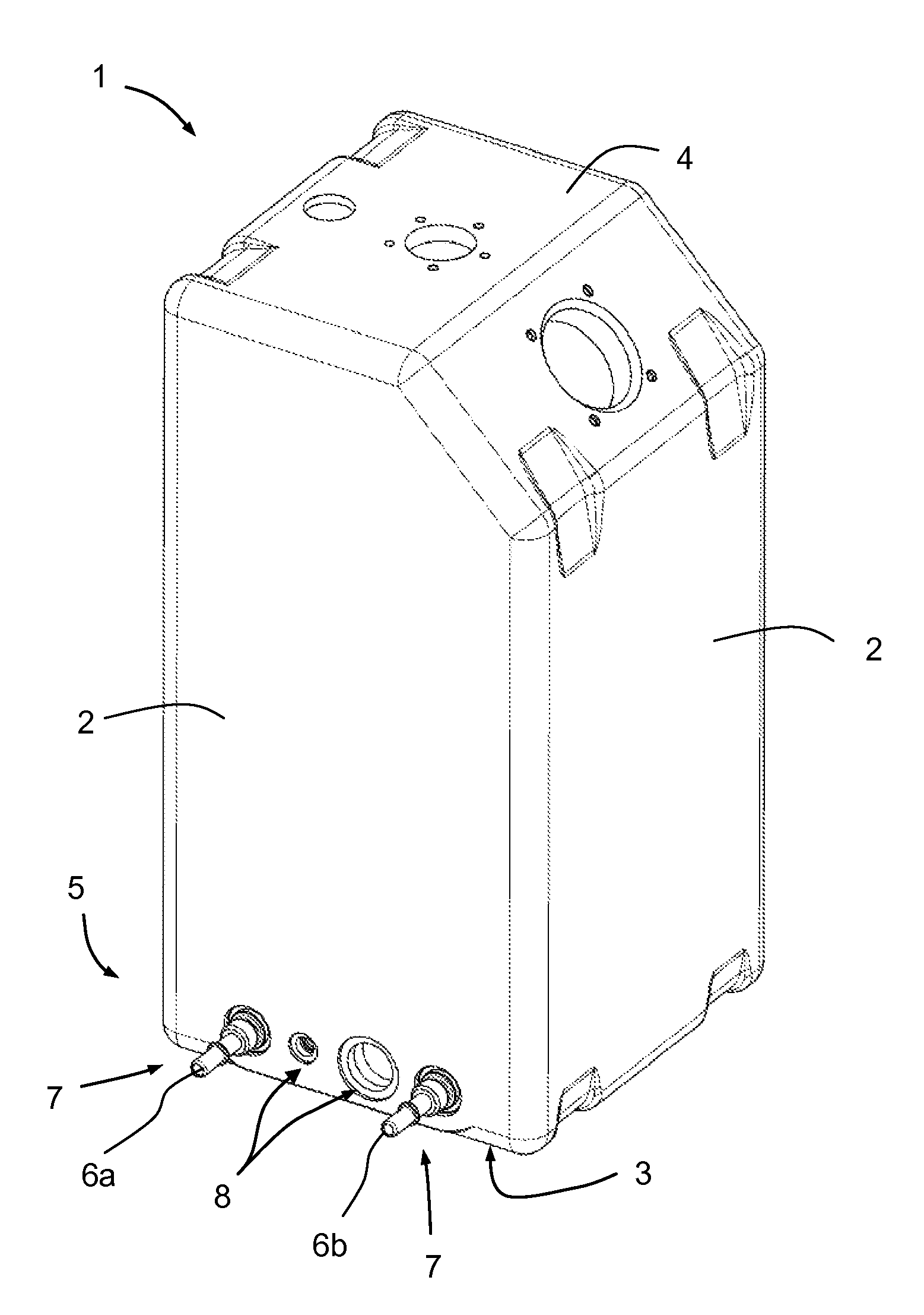
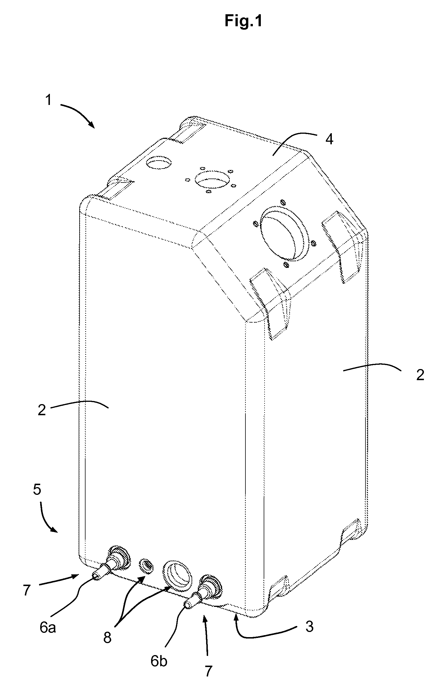
[0020]The liquid container 1 shown in FIG. 1 is initially formed by side walls 2, a lower container wall 3 and an upper container wall 4. Upper container wall 4 has one horizontal and one sloping section. Apertures are formed in each of the sections, and these may be used for example as filling and emptying apertures, but also as connection ports for additional devices such as fill level sensors, temperature gauges, or quality sensors. Connector ends 6a and 6b of a heating element 10 located inside liquid container 1 pass out through the lower area of container side wall 2, base area 5 of the liquid container 1. Connector ends 6a, 6b are each individually equipped with adapters 7 for connection to a suitable heat source, and are each separately encased in the container side wall in sealing manner by sintering. Further connection apertures 8 are also created to allow connection of other suitable devices as desired.

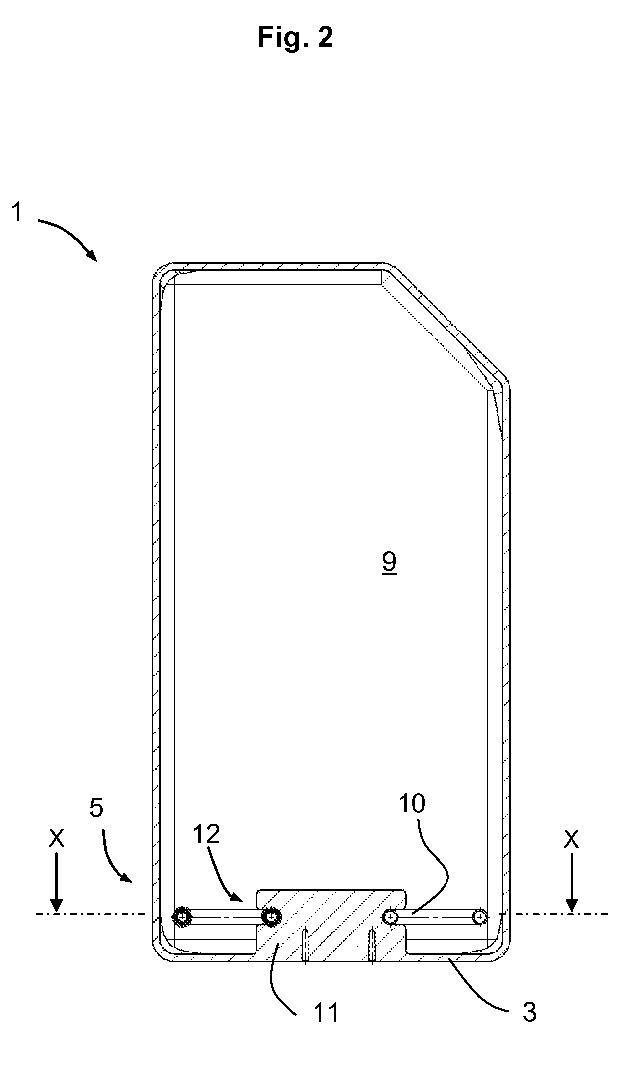
[0021]FIGS. 2 and 3 illustrate the construction of liquid container 1 ...


PUM


Abstract

A heatable liquid container made from plastic material, particularly for holding water / urea mixtures and having an internal cavity and a heating element arranged essentially in the internal cavity of the container, and with at least one connection end, the heating element is braced by a bracing element in at least one bearing area in the internal cavity of the liquid container. The heating element is supported in a horizontally floating manner by the bracing element. The bracing element is an insert part that is at least partially encased in the plastic material by sintering and is made from the same material as the inner wall of the liquid container.

Description

PRIORITY[0001]This application claims the benefit of German Application No. 10 2009 040 930.0-13, filed Sep. 11, 2009, which application is hereby incorporated by reference in its entirety.FIELD OF THE INVENTION[0002]The invention relates to a heatable liquid container made from plastic material, for example thermoplastic materials such as polyethylene (PE), cross-linked polyethylene (XPE), polypropylene (PP), polyamide 6, 11 or 12 (PA 6, PA11 or PA12) or similar, particularly for holding water / urea mixtures, having a heating element that is arranged essentially in the internal cavity of the container and has at least two connection ends, wherein the heating element is braced by a bracing element in at least one bearing area inside the liquid container.BACKGROUND OF THE INVENTION[0003]Regulations governing emission limits for combustion engines, particularly in motor vehicles, are becoming increasingly stringent. Among the methods used to satisfy these requirements, catalytic conver...

Claims


Application Information

Patent Timeline
Patent Type & Authority Patents(United States)
IPC IPC(8): A47J27/00
CPCF01N3/2066F01N2610/02F01N2610/10F01N2610/1406Y02T10/24Y02T10/12
Inventor BIER, VOLKERPRINZ, THOMAS
Owner ELKAMET KUNST GMBH
Why Eureka
Try Eureka