Eureka AIR delivers breakthrough ideas for toughest innovation challenges, trusted by R&D personnel around the world.

Level sensors

a level sensor and level sensor technology, applied in the direction of level indicators by physical variable measurement, liquid/fluent solid measurement, engine lubrication, etc., can solve the problems of insufficient resolution, excessively expensive sensors which operate accurately over a predetermined range, and inadequate range of level sensors

Inactive Publication Date: 2005-08-09
PROD INNOVATION
View PDF14 Cites 50 Cited by
  • Summary
  • Abstract
  • Description
  • Claims
  • Application Information

AI Technical Summary

Benefits of technology

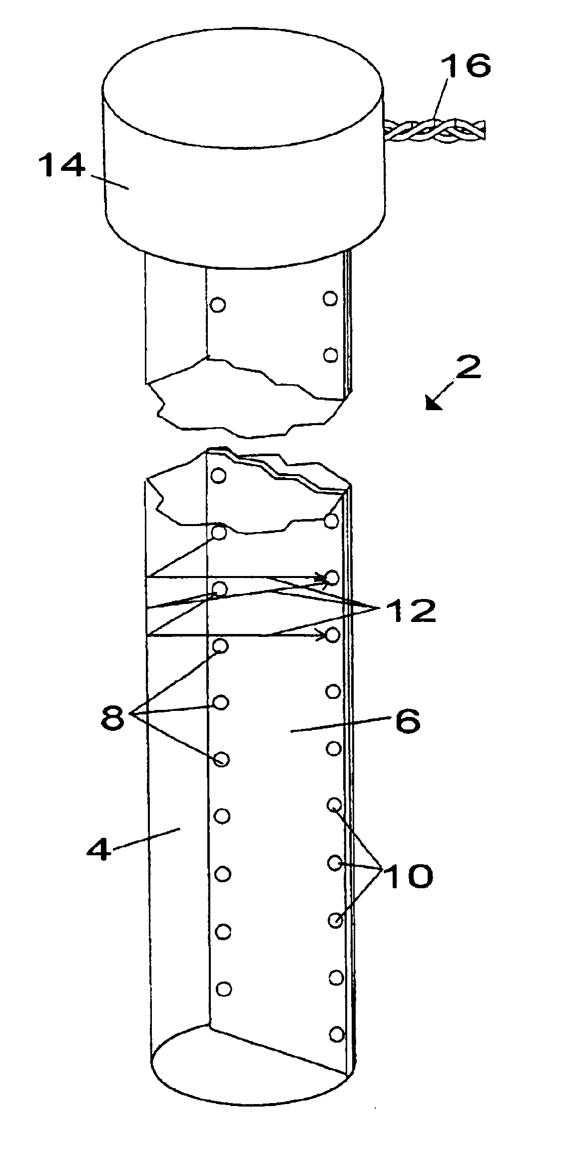
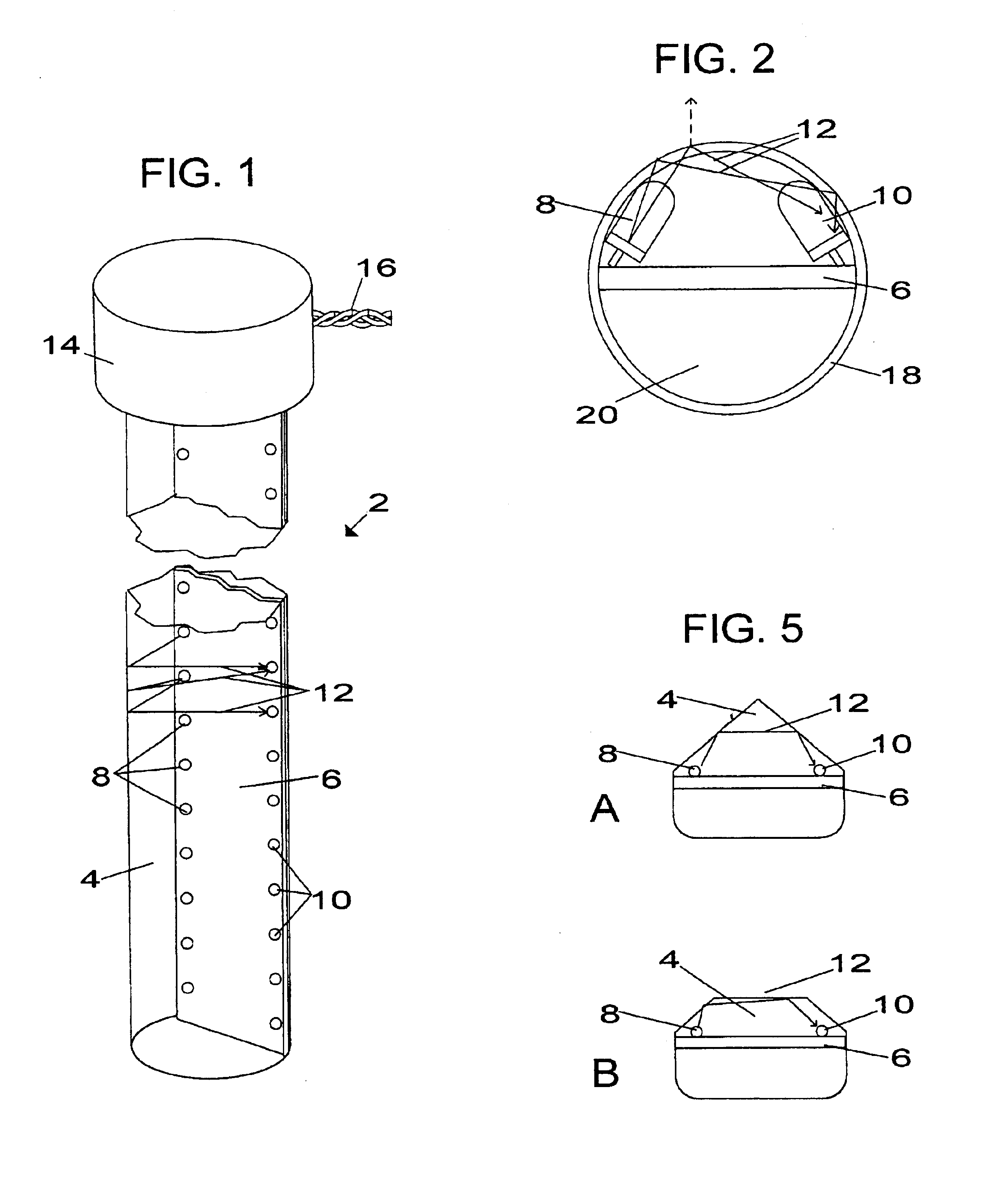
[0009]Such an arrangement provides for ease of manufacture, especially if the housing is formed using a moulding, extrusion or potting process. An inexpensive unitary device provides for detection of various different levels. Using a continuous, preferably straight external surface means that the positions of the emitters and receivers with respect to the length of the housing are not critical, and also facilitates cleaning of the sensor, which can be very important in certain environments, such as those involving foodstuffs. These advantages are further enhanced if, in accordance with a preferred aspect of the invention, the outside profile of the housing is substantially uniform throughout the length over which level sensing takes place.
[0011]Further preferred features of the invention enable additional cost reduction and ease of manufacture.
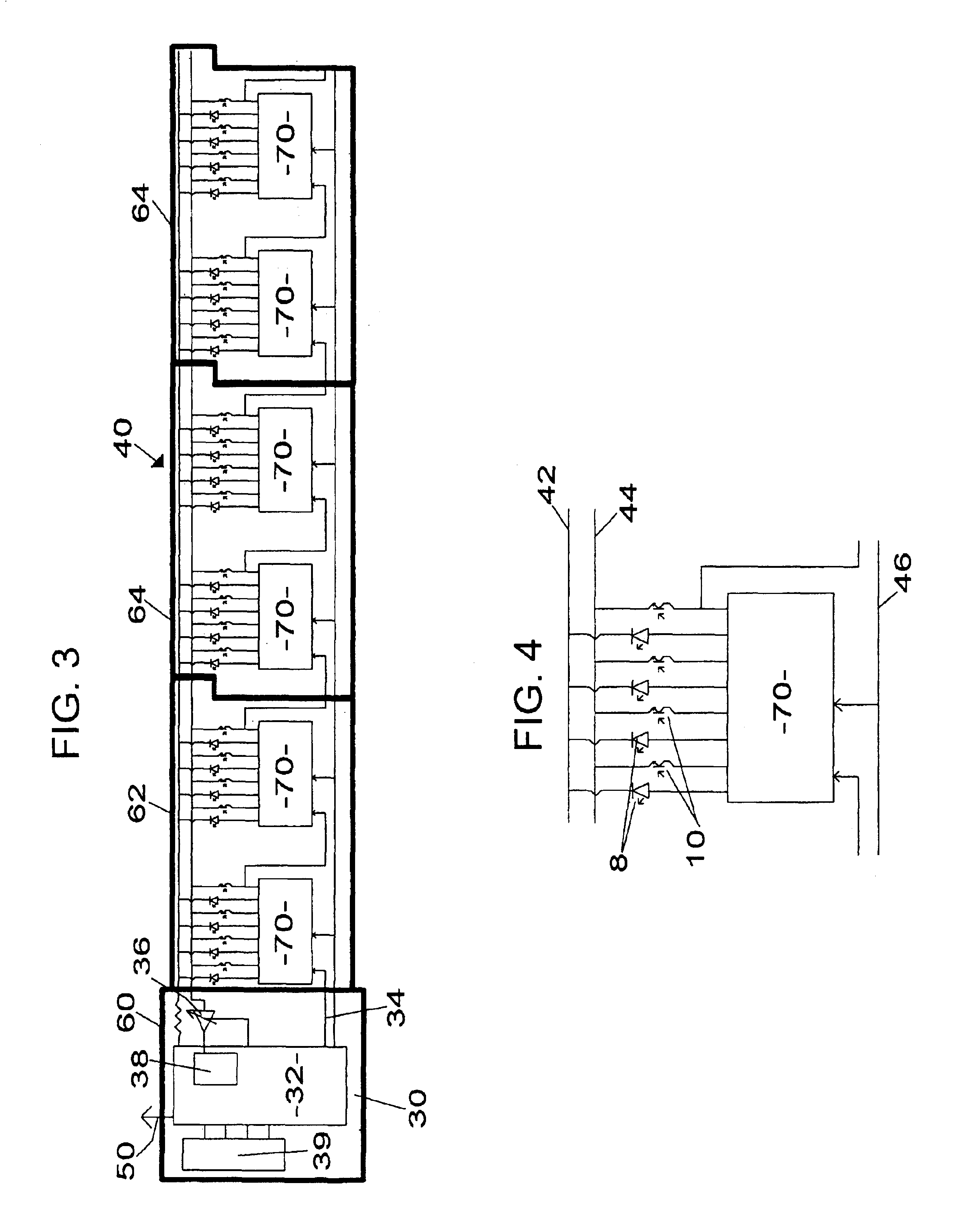
[0012]According to one preferred feature, the emitters and receivers are respectively driven and enabled by at least one shift register. Use of a shift register (which can be implemented using very inexpensive components) reduces the wiring requirements of the circuit as compared with providing individual driving and enabling circuits. There may be respective shift registers for the emitters on the one hand and the receivers on the other hand. However, the preferred embodiment incorporates a shift register which both drives the emitters and enables the receivers.
[0013]According to a further preferred feature of the invention, the circuit for operating the level sensor comprises a plurality of individual circuit boards of identical, modular construction, each circuit board containing a portion of the shift register. This means that level sensors of differing lengths can be built using common components, by appropriate selection of the number of modular circuit boards, thus reducing costs.
[0014]According to a further preferred feature of the invention, each receiver is operable to receive light from at least two emitters at respective different heights, the emitters being, in use, operated at different time intervals. Thus, a single receiver can indicate whether or not the liquid has reached any of two different levels. Additionally, or alternatively, each emitter is arranged to illuminate two separate receivers, each of which can be enabled in respective different periods. Accordingly, a single emitter can be used for determining whether the liquid has reached either of two different levels. By combining these features, for a given resolution, the number of emitters and receivers can be halved, thus further reducing costs.
[0017]According to a further preferred feature of the invention, the effects of ambient light are compensated when evaluating the outputs of the light receivers by taking a separate ambient light measurement. In the preferred embodiment, each reading from an emitter / receiver pair is compensated by a separate reading from the same receiver without the respective emitter being operated; that is, individual ambient readings are taken for the different receivers. In a particularly preferred embodiment, the ambient reading is combined with the calibration data mentioned above in order to compensate both for individual variations in circuit components and ambient light.

Problems solved by technology

Some level sensors operate over an inadequate range, and others with inadequate resolution.
Sensors which operate accurately over a predetermined range can be excessively expensive, particularly for wider ranges.
In some cases, the structure or physical principles of operation are incompatible with the environment in which the sensor is intended to be used.
Such arrangements are not, however, suitable for indicating varying liquid levels.
However, this would be expensive and difficult to assemble.
The physical size of each switch would preclude the possibility of mounting them in close proximity, thus resulting in an arrangement which is lacking in resolution and / or compactness.

Method used


Image

  • Level sensors
  • Level sensors
  • Level sensors

Examples


Embodiment Construction

[0007]Aspects of the present invention are set out in the accompanying claims.

[0008]According to a further aspect of the invention, a level sensor incorporates an array of light emitters arranged along a direction which, in use, is at least approximately vertical, and an array of light receivers distributed along a substantially parallel direction, each receiver being operable to receive light from at least one emitter. The emitter and receiver arrays have a common transparent housing which is capable of totally internally reflecting light from the emitters to the receivers by an external surface which is preferably continuous and straight in the aforementioned direction.

[0009]Such an arrangement provides for ease of manufacture, especially if the housing is formed using a moulding, extrusion or potting process. An inexpensive unitary device provides for detection of various different levels. Using a continuous, preferably straight external surface means that the positions of the em...


PUM

PropertyMeasurementUnit
refractive indicesaaaaaaaaaa
refractive indexaaaaaaaaaa

Abstract

A level detector comprises an array of light emitting devices mounted in a line parallel to an array of light receiving devices, the arrays being mounted within a housing capable of internally reflecting light from the emitting devices to respective receiving devices unless the respective parts of the level sensor are immersed in liquid. The outer internally-reflecting surface of the housing is preferable a continuous straight-line surface along the direction parallel to the arrays.

Description

CROSS REFERENCE TO RELATED APPLICATION[0001]This application claims priority from European Patent Application No. 02254951.3, filed Jul. 15, 2002.FIELD OF THE INVENTION[0002]This invention relates to a method and apparatus for measuring liquid levels.BACKGROUND OF THE INVENTION[0003]Many different types of level sensors are available, and these rely upon a variety of different physical principles. One reason for the large variety of sensors is that level sensors are required in numerous different environments for many different purposes, and few level sensors are versatile enough to have a wide range of use. Thus, for example, some level sensors merely detect whether or not liquid has exceeded a predetermined level, whereas some applications require measurement of liquid level throughout a range. Some level sensors operate over an inadequate range, and others with inadequate resolution. Sensors which operate accurately over a predetermined range can be excessively expensive, particu...

Claims


Application Information

Patent Timeline
Patent Type & Authority Patents(United States)
IPC IPC(8): G01F23/292G01F23/284
CPCG01F23/2921Y10S250/90
Inventor FRANK, PETER
Owner PROD INNOVATION
Why Eureka
Eureka Blog
Learn More