Device for and method of signal synchronization in a communication system

a communication system and signal synchronization technology, applied in the direction of synchronisation signal speed/phase control, pulse technique, amplitude demodulation, etc., can solve the problems of loss of information regarding cst, signal transmission from base stations to terminals via physical channels (such as air) in a communication system, and may not know the start of each fram

Active Publication Date: 2009-05-28
IND TECH RES INST
View PDF13 Cites 55 Cited by
  • Summary
  • Abstract
  • Description
  • Claims
  • Application Information

AI Technical Summary

Benefits of technology

[0013]Examples of the present invention may further provide a device for signal synchronization in a communication system, the device comprising a first detector configured to perform a first sliding correlation for a received signal and a pseudo-random noise (PN) sequence to obtain a coarse symbol timing (CST), a second detector configured to identify a fractional carrier frequency offset (FCFO) using the CST and the cyclic extension property of the PN guard interval (GI), a first multiplier configured to provide a first product by multiplying the received signal with the FCFO to compensate for the effect of the FCFO, and a third detector comprising a set of second multipliers configured to provide a set of second products by multiplying the first product with one of a set of phases related to integral carrier frequency offsets (ICFOs), a set of sliding correlators configured to perform a set of second sliding correlations for the PN sequence and the set of second products, the set of sliding correlators being capable of providing a set of peak values, and a peak detector configured to receive a set of peak values related to the ICFOs from the set of sliding correlators and identify an ICFO by detecting an index number of a maximal value among the set of peak values.

Problems solved by technology

Furthermore, the terminal may not know the start of each frame for a given base station, the time at which each frame is transmitted by the base station, or the propagation delay introduced by the communication channel.
Due to non-ideal channel effects, for example, multi-path reflection and multi-path fading, signals transmitted from base stations to terminals via physical channels (such as air) in a communication system may be distorted.
However, the desirable autocorrelation characteristics of a PN sequence may be susceptible to carrier frequency offset (CFO), which may attenuate the peak value of an output of a sliding correlator. FIGS. 2A and 2B are schematic diagrams illustrating phase distribution in the autocorrelation of a PN sequence due to a relatively small CFO and a relatively large CFO, respectively.
If the value of the maximum output peak of a sliding correlator is attenuated, information regarding CST may be lost.
The communication system 1 may alleviate the CFO issue, however, the system structure may be complicated because the differential modulator 12 is required for each base station in the system 1.

Method used


Image

  • Device for and method of signal synchronization in a communication system
  • Device for and method of signal synchronization in a communication system
  • Device for and method of signal synchronization in a communication system

Examples


Embodiment Construction

[0030]Reference will now be made in detail to the present examples of the invention illustrated in the accompanying drawings. Wherever possible, the same reference numbers will be used throughout the drawings to refer to the same or like portions.

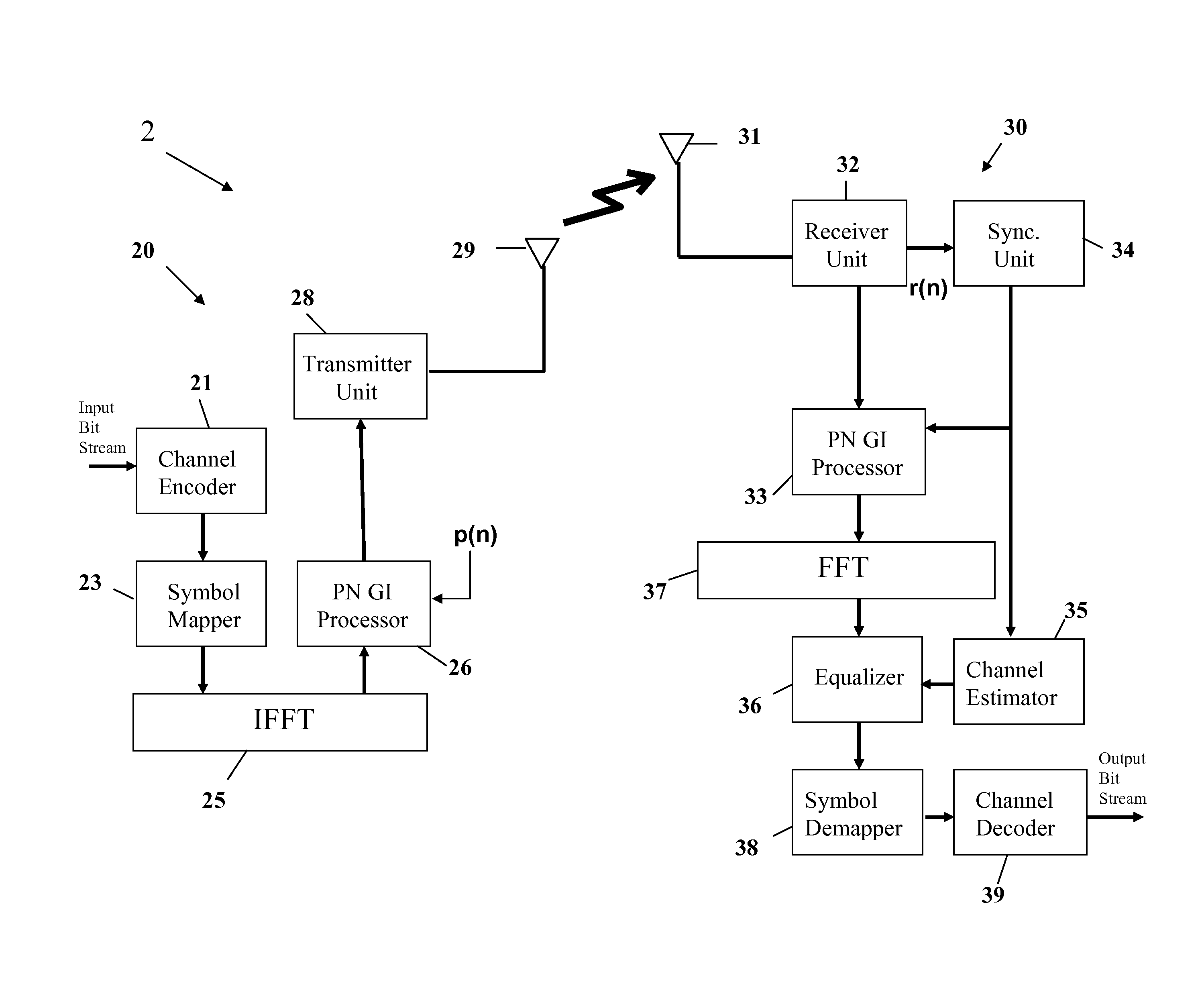
[0031]FIG. 4 is a block diagram of a communication system 2 where examples of the present invention may be implemented. Referring to FIG. 4, the communication system 2 may include a base station 20 and a terminal 30, which may be a base station and a mobile station in the communication system 2, respectively. In one example, the communication system 2 may include one of an Asymmetric Digital Subscriber Line (ADSL), Power Line Communication (PLC), Digital Audio Broadcasting (DAB) systems, systems adopting Wireless Local Area Network (WLAN) 802.11a / b / g / n, Digital TV System (DVB-T and DVB-H) standards and the future 4G personal communication system. In another example, the communication system 2 may utilize Orthogonal Frequency Division Multip...


PUM


Abstract

A device for signal synchronization in a communication system, the device comprising a first detector configured to perform a first sliding correlation for a received signal and a pseudo-random noise (PN) sequence to obtain information on symbol timing, a second detector configured to identify a fractional carrier frequency offset (FCFO) using the information on symbol timing and the cyclic extension property of the PN guard interval (GI), a first multiplier configured to provide a first product by multiplying the received signal with the FCFO, and a third detector comprising a set of second multipliers configured to provide a set of second products by multiplying the first product with each of a set of phases related to integral carrier frequency offsets (ICFOs), a set of sliding correlators each being configured to perform a second sliding correlation for the PN sequence and one of the set of the second products, the set of sliding correlators providing a set of peak values, and a peak detector configured to identify an ICFO by detecting an index number of a maximal value among the set of peak values.

Description

BACKGROUND OF THE INVENTION[0001]The present invention relates to signal synchronization in a communication system and, more particularly, to a device for and a method of signal synchronization in an orthogonal frequency division multiplexing (OFDM) system using pseudo-random noise (PN) guard intervals (GIs).[0002]In a communication system, a base station may process (e.g., encode and symbol-map) data to obtain modulation symbols, and may further process the modulation symbols to generate a modulated signal. The base station then transmits the modulated signal via a communication channel. The communication system may use a transmission scheme whereby data are transmitted in frames, with each frame having a particular time duration. Different types of data, such as traffic / packet data, overhead / control data and pilot, may be sent in different parts of each frame.[0003]A terminal in the system may not know which base stations, if any, near its vicinity are transmitting. Furthermore, t...

Claims


Application Information

Patent Timeline
Patent Type & Authority Applications(United States)
IPC IPC(8): H04L7/00H04J11/00H04B1/00
CPCH04L27/2662H04L27/2678H04L27/266H04L27/2659
Inventor SHEU, CHORNG-REN
Owner IND TECH RES INST
Why Eureka
Try Eureka