Target comprising thickness profiling for an RF magnetron

a technology of rf magnets and target plates, applied in the direction of electrodes, diaphragms, ion implantation coatings, etc., can solve the problems of increasing the sputter rate of regions, and achieve the effect of increasing the sputter rate, and having a special type of correction capability

Inactive Publication Date: 2005-07-12
ESEC
View PDF3 Cites 56 Cited by
  • Summary
  • Abstract
  • Description
  • Claims
  • Application Information

AI Technical Summary

Benefits of technology

[0009]It was found that the capacitance developing between metallic conducting bonding plate and the plasma developing in the front region of the target is different if the dielectric target is developed of different thickness with respect to the bond plate in subregions of the target. It thereby becomes possible to affect locally the discharge or the discharge density. Through this approach the sputter distribution can be affected if in the desired regions the target thickness is varied over the target face. In the thinner region the capacitance between plasma and target support plate is increased, which also results in these regions in an increase of the sputter rate. Through the corresponding profiling of the target, consequently, the distribution can be affected to the desired extent. This type of correction capability is especially favorable when using magnetron sputter sources, which develop inherently different erosion profiles through the magnetic field-enhanced plasma generation and these erosion profiles, generated by the magnetic field, effect distribution profile shifts over the target working life. For example, in regions of strong erosion due to the magnetic field this pronounced erosion can be compensated by a thickening of the target via the capacitive effect. In regions of the weaker erosion by the magnetic field through a thinning of the target an increase of the sputter rate is brought about. Consequently, a compensation of the effect is also possible. Profiling of the target can take place for example on the front side facing the plasma, and the target support plate can be shaped on the back side as a planar plate. A further option also comprises profiling the support plate and to dispose between a flat target plate and the profiled support plate a further dielectric with good thermal conductivity, which is more readily workable than the target material itself and consequently represents a compensation dielectric with the advantage that the brittle target material itself can be implemented as simple as possible for example as a planar plate. The previously cited profiling options can also be combined. But for reasons of simple manufacture those solutions are preferred which permit the simplest possible contours or even permit a purely plate-form target, wherewith the production process can be carried out economically. Apart from simple depressions or elevations, other forms of profiling also have an effect such as for example trapezoidal, spherical, toroidal ribs or grooves. With the profiling thus the erosion rate, but in particular the radial distribution of the erosion rate in round targets, can be stabilized over the entire target working life. When sputtering conductive target materials with RF or DC sputtering, this effect does not occur.

Problems solved by technology

In the thinner region the capacitance between plasma and target support plate is increased, which also results in these regions in an increase of the sputter rate.

Method used


Image

  • Target comprising thickness profiling for an RF magnetron
  • Target comprising thickness profiling for an RF magnetron
  • Target comprising thickness profiling for an RF magnetron

Examples


Embodiment Construction

.

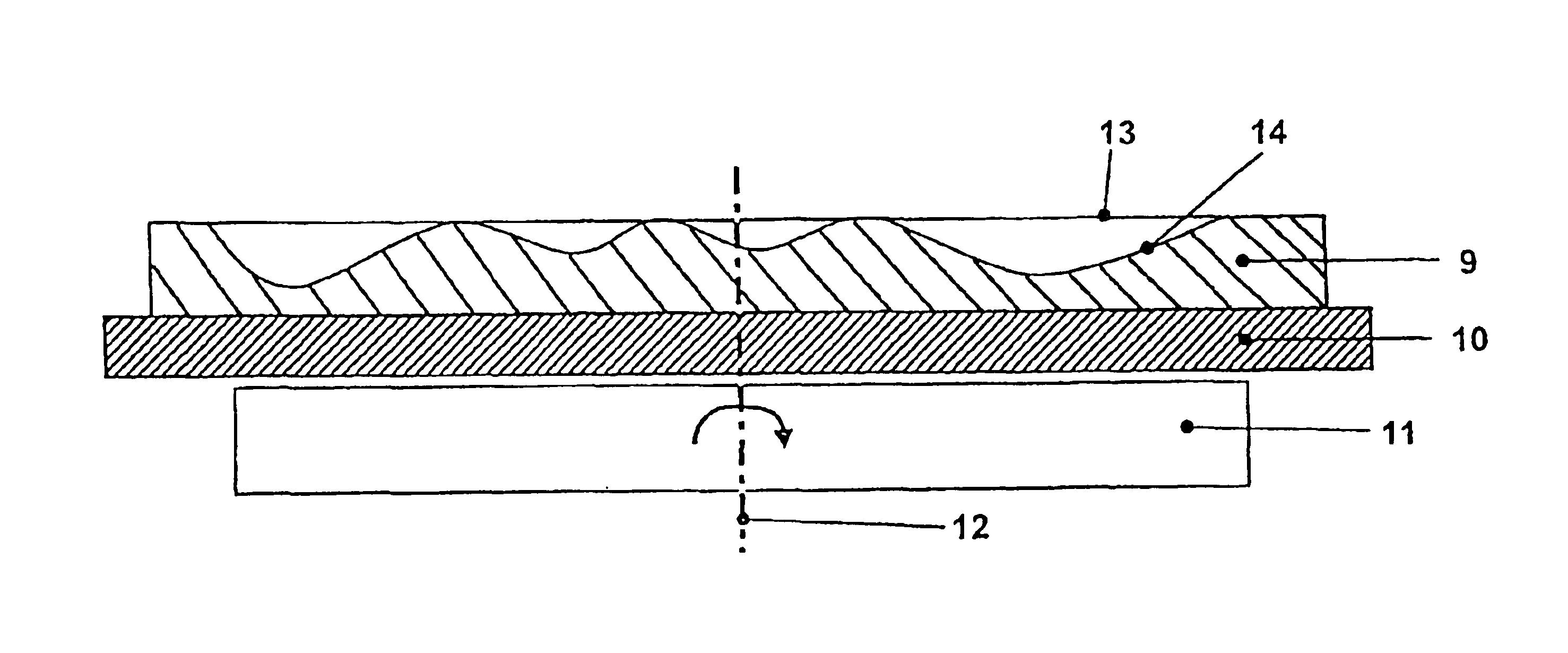
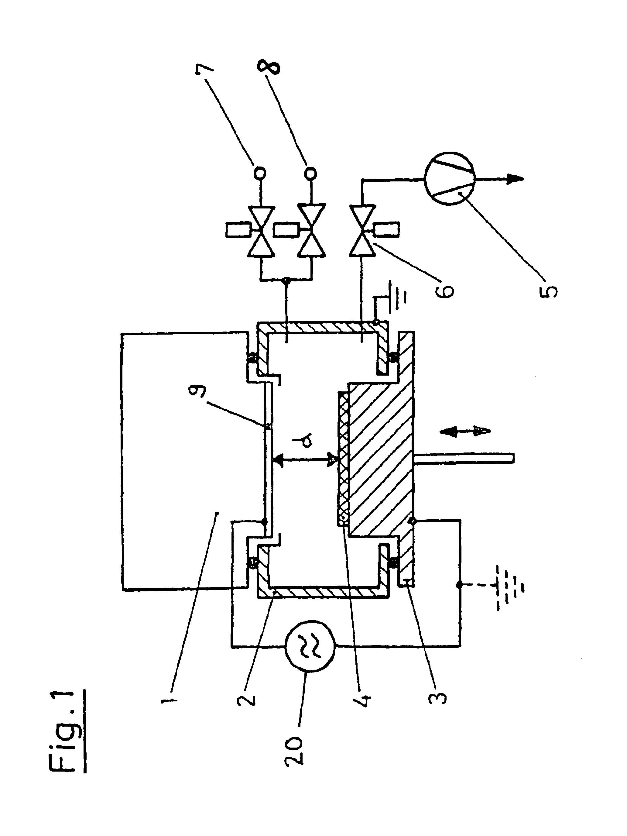
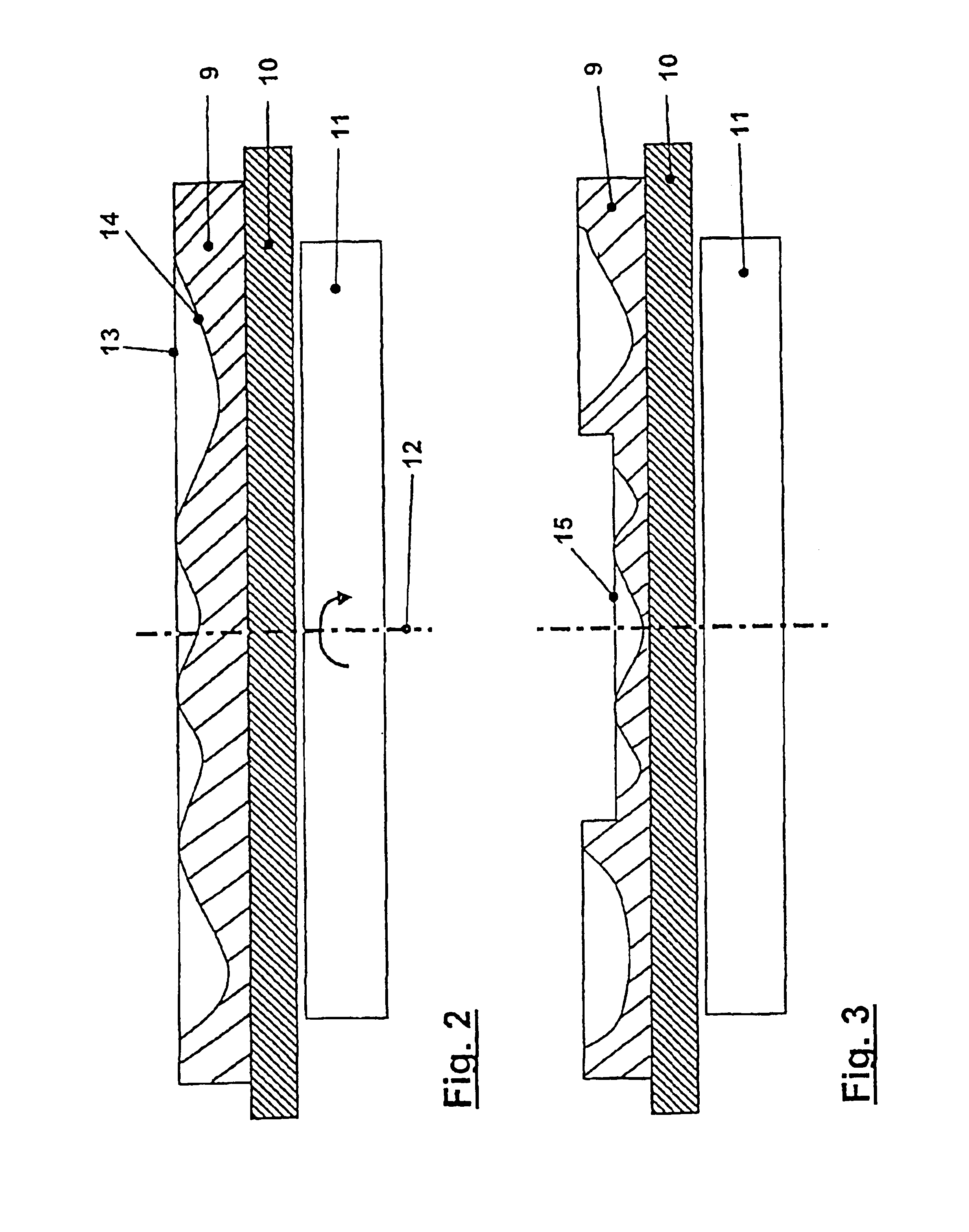
[0023]High frequency sputtering sources for vacuum coating processes are employed in varied manner. Especially the magnetron sputtering technique with magnetic field-enhanced plasma generation is preferably employed due to the high attainable rates and due to the capability of affecting the sputtering characteristic via the magnetic field. Sputtering sources of this type can be developed in different geometries, for example tubular with target tubes also rotating, planar with targets disposed a really, such as rectangular cathodes, or also round cathode configurations, or also as cathodes developed in the form of an arch or those developed hollow. In order to attain a good distribution of the deposited layer, the workpieces or the substrates to be coated can be moved with respect to the sputtering target. But they are often used for fully automated installations, so-called static coating configurations, in which the workpiece is stationarily disposed at a distance of a few centimet...


PUM

PropertyMeasurementUnit
frequencyaaaaaaaaaa
frequencyaaaaaaaaaa
frequencyaaaaaaaaaa

Abstract

Method for sputtering from a dielectric target (9) in a vacuum chamber (2) with a high frequency gas discharge, the target (9) being mounted on a cooled metallic back plate (10) and this back plate forming an electrode (10) supplied with high frequency, includes a target thickness (Td) profiled (15) differently over the surface such that in the regions of a desired decrease of the sputtering rate the target thickness (Td) is selected to be greater than in the remaining regions.

Description

FIELD AND BACKGROUND OF THE INVENTION[0001]The present invention relates to a method for sputtering a dielectric target in a vacuum chamber with a high frequency gas discharge, as well a sputter target and a magnetron sputter source with a corresponding sputter target. The dielectric layer is deposited onto a workpiece, in particular a synthetic workpiece, with the aid of the known high frequency cathode sputtering method, in particular with magnetron sputtering in a vacuum chamber. Such layers are in particular applied in the production of storage plates. Among them for example optical recording methods, where the information is impressed in the plate itself and is provided with a highly reflecting layer, with a laser beam being capable of scanning the information correspondingly. In particular in the vacuum coating of optical disks with the aid of the static sputtering method with round cathode configurations with nonconducting materials, and especially in the coating of rewritabl...

Claims


Application Information

Patent Timeline
Patent Type & Authority Patents(United States)
IPC IPC(8): C23C14/34H01J37/34H01J37/32G11B7/26
CPCC23C14/3407H01J37/3408H01J37/3423
Inventor VOSER, STEPHANLORENZ, EDUARD KARL
Owner ESEC
Why Eureka
Try Eureka