Compensating for effects of variations in gas refractivity in interferometers

Inactive Publication Date: 2005-01-11
ZYGO CORPORATION
View PDF5 Cites 55 Cited by
  • Summary
  • Abstract
  • Description
  • Claims
  • Application Information

AI Technical Summary

Benefits of technology

Some embodiments may enable rapid and accurate compensation of the optical path length effects of a gas in a measurement path and/or a reference path wherein the accuracy of compensation of optical path length effects of the gas are substantially not compromised by a rapid change in physical length of measurement and/or reference paths.
In some embodiments, optical path length effects of a gas can be compensated rapidly and accurately without requiring measur

Problems solved by technology

However, in many systems, it is not practical to place a refractometer or other means for measuring the gas refractivity at or nearby the measurement beam path.
However, interferometers are used for high-precision measurements in many systems where the atmosphere is rarely in equilibrium, and such a one-to-one mapping of the measured refractivity to the refractivity in the measurement beam path is not sufficiently accurate.
During the operation of such a system, the gas environment can frequently change.
Scanning or stepping the wafer and/or reticle during an exposure cycle can also cause gas movement in the system.
In addition, temperature changes during an exposure cycle can affect environmental parameters like humidity and density, which can both

Method used


Image

  • Compensating for effects of variations in gas refractivity in interferometers
  • Compensating for effects of variations in gas refractivity in interferometers
  • Compensating for effects of variations in gas refractivity in interferometers

Examples


first embodiment

Referring to FIG. 3, an interferometry system 200 includes an interferometer generally depicted at numeral 210. Interferometer 210 is a polarizing, heterodyne, single pass interferometer. This configuration is known in the art as a polarized Michelson interferometer, and is shown as a simple illustration. Although the first embodiment comprises a heterodyne system, the interferometry system is readily adapted for use in a homodyne system in which the reference and measurement beams have the same frequencies before introduction of any Doppler shifts. While the apparatus has application for a wide range of radiation sources, the following description is taken by way of example with respect to an optical measuring system.

A first portion of light beam 222 emitted from source 220 is transmitted by non-polarization beam-splitter 242 to form beam 224. A second portion of beam 222 is reflected by non-polarization beam-splitter 242 to form beam 232 after reflection by mirror 244. The descrip...

third embodiment

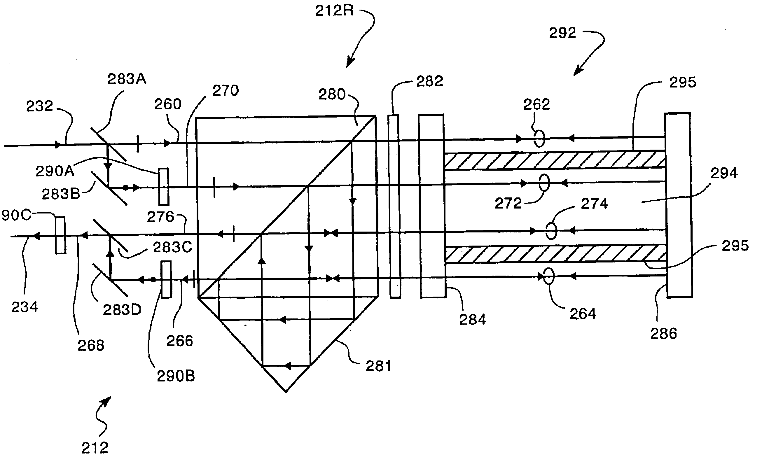
Another procedure for testing the properties of density profile ratio ρ(x,y,z,t) / ρ(x0,y0,z0,t) for accuracy is by interferometric measurements made with additional interferometers. Measurement paths of the additional interferometers may comprise fixed or variable physical lengths that intersect or pass near the measurement path of interferometer 210 and measuring the corresponding changes in optical path length(s) and the refractivity measured by monitor 212. The additional interferometers may also comprise angle measuring interferometers and measuring corresponding changes in directions of propagation of the measurement beams of the additional interferometers such as subsequently described with respect to the present invention and the refractivity measured by monitor 212.

Other embodiments of interferometry systems can include a wavelength monitor. Such systems can compensate interferometry measurements for changes in λ1, in addition to changes in the gas refractivity. Referring to ...


PUM


Abstract

Methods and system for compensating for effects of changes and variations of gas refractivity in a measurement and/or reference beam path of an interferometer are disclosed.

Description

BACKGROUNDDisplacement measuring interferometers monitor changes in the position of a measurement object relative to a reference object based on an optical interference signal. The interferometer generates the optical interference signal by overlapping and interfering a measurement beam reflected from the measurement object with a reference beam reflected from the reference object.In many applications, the measurement and reference beams have orthogonal polarizations and different frequencies. The different frequencies can be produced, for example, by laser Zeeman splitting, by acousto-optical modulation, or internal to the laser using birefringent elements or the like. The orthogonal polarizations allow a polarizing beam splitter to direct the measurement and reference beams to the measurement and reference objects, respectively, and combine the reflected measurement and reference beams to form overlapping exit measurement and reference beams. The overlapping exit beams form an out...

Claims


Application Information

Patent Timeline
IPC IPC(8): G01B9/02G03F7/20G01B11/00G01N21/27H01L21/027
CPCG03F7/70775G03F7/70883G01B9/02003G01B9/02052G01B9/0207G01B2290/45G01B2290/70
Inventor HILL, HENRY A.
Owner ZYGO CORPORATION
Why Eureka
Try Eureka