Apparatus and method for compensating output signals of magnetic encoder using digital phase-locked loop

a phase-locked loop and output signal technology, applied in the field of magnetic encoders, can solve the problems of low resolution of two output signals of magnetic encoders, inability to easily manufacture in a small size, and the optical encoder is vulnerable to a change in temperature and dust, so as to achieve rapid and accurate compensation

Active Publication Date: 2015-10-13
FASTECH
View PDF3 Cites 3 Cited by
  • Summary
  • Abstract
  • Description
  • Claims
  • Application Information

AI Technical Summary

Benefits of technology

[0011]Accordingly, the present invention has been made to address the above problems occurring in the prior art, and an object of the present invention is to provide an apparatus and method for compensating output signals of a magnetic encoder using a digital phase-locked loop (PLL) in order to perform rapid and accurate compensation.

Problems solved by technology

However, the optical encoder is vulnerable to a change in temperature and dust, cannot be easily fabricated in a small size, and is expensive.
However, although the magnetic encoder is inexpensive, two output signals of the magnetic encoder have low resolution because they are vulnerable to noise, phase drift, DC offset, amplitude variation, and waveform distortion.
For example, a method using a Kalman filter widely used to eliminate noise from sampling data in a high noise environment, or a method using an observer has been proposed, but a problem arises in that phase drift is unsolvable or an excessive time is required to settle.

Method used


Image

  • Apparatus and method for compensating output signals of magnetic encoder using digital phase-locked loop
  • Apparatus and method for compensating output signals of magnetic encoder using digital phase-locked loop
  • Apparatus and method for compensating output signals of magnetic encoder using digital phase-locked loop

Examples


Embodiment Construction

[0060]In the following description of embodiments of the present invention, specific structural and functional descriptions are provided merely for the purpose of illustrating the embodiments of the present invention, and the present invention may be practiced in various forms and should not be construed as being limited to the embodiments herein.

[0061]Example embodiments of the present invention are described in greater detail below with reference to the accompanying drawings. The same reference numerals are assigned to the same components throughout the drawings, and redundant descriptions of the same components are omitted.

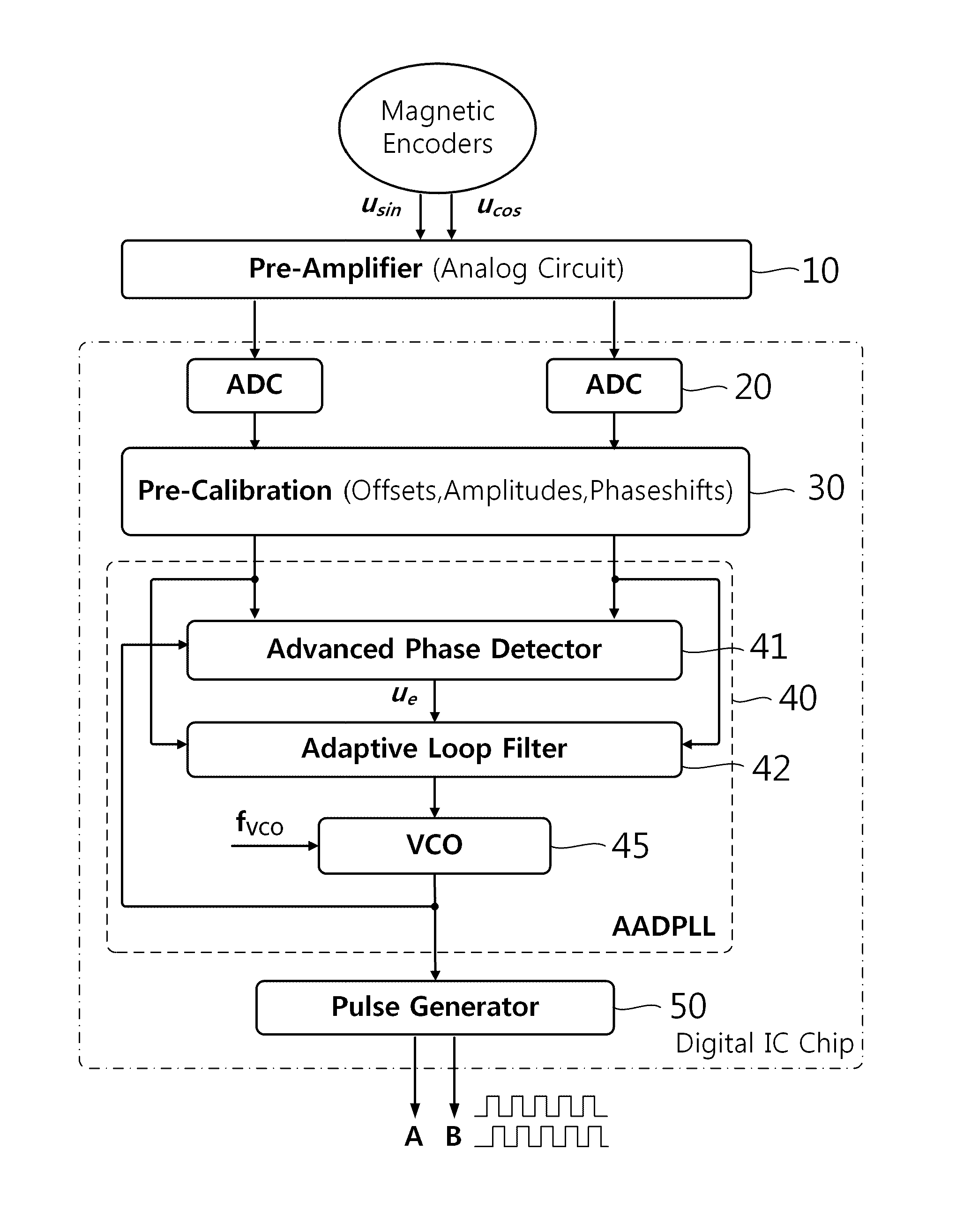
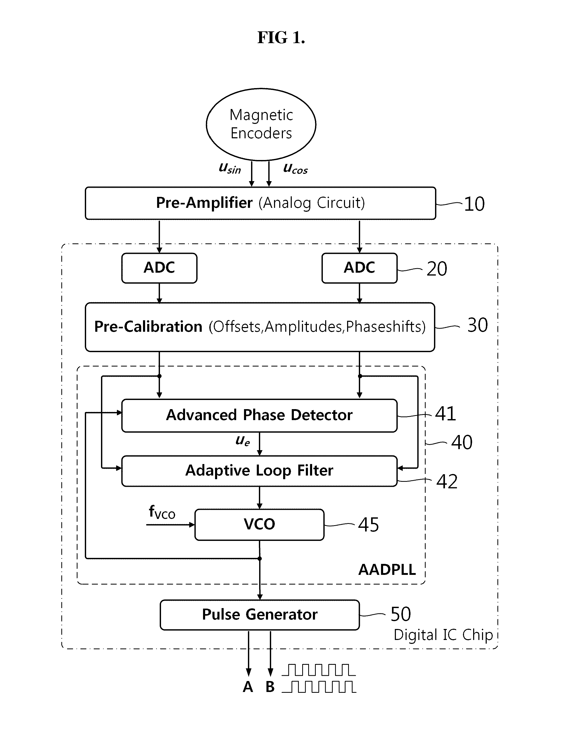
[0062]FIG. 1 is a schematic block diagram of an output signal compensation apparatus for compensating output signals of a magnetic encoder using a digital PLL according to an embodiment of the present invention.

[0063]Referring to FIG. 1, the output signal compensation apparatus 1 of a magnetic encoder (ME) may include a pre-amplifier 10, an analog digital conve...


PUM


Abstract

An apparatus and method for compensating output signals of a magnetic encoder are disclosed. The apparatus includes a pre-calibration unit, an advanced phase detector, a loop filter, a voltage controlled oscillator (VCO), and a pulse generator. The pre-calibration unit obtains two phase-compensated waveforms through trigonometric function operations, and adjusts the amplitudes of the two phase-compensated waveforms to the same value, thereby generating input sine and cosine waves. The advanced phase detector generates an error output signal through trigonometric function operations. The loop filter sets the filter transfer function of an active lead-lag filter, and then filters the error output signal. The VCO generates a compensated signal. The pulse generator outputs a phase index, and generates two output pulses having a phase difference of 90 degrees in accordance with a pulse generation rule of a look-up table.

Description

CROSS-REFERENCE TO RELATED APPLICATION(S)[0001]This application claims the benefit under 35 USC 119(a) of Korean Patent Application No. 10-2013-0089183 filed on Jul. 26, 2013, in the Korean Intellectual Property Office, the entire disclosure of which is incorporated herein by reference for all purposes.BACKGROUND OF THE INVENTION[0002]1. Field of the Invention[0003]The present invention relates generally to a magnetic encoder and, more particularly, to technology for compensating output signals of a magnetic encoder.[0004]2. Description of the Related Art[0005]In various industrial fields, sensors for detecting the rotational angular velocity and location of a rotating object are required. For this purpose, an optical encoder and a magnetic encoder are chiefly used.[0006]An optical encoder has slots rotating in synchronization with a rotating object and passing between an optical source such as laser and an optical receiver, and can generate output signals for detecting the rotation...

Claims


Application Information

Patent Timeline
Patent Type & Authority Patents(United States)
IPC IPC(8): H03D3/24G01P3/487H04L1/00
CPCG01P3/487H04L1/0042G01D5/2448G01P3/489G01P3/44
Inventor JEON, JAE WOOKCHO, SEONG JINHUNG, HOANG VAN
Owner FASTECH
Why Eureka
Try Eureka