Filter device

a filter device and conduit technology, applied in the direction of dispersed particle filtration, tyre-inflating valve, tire measurement, etc., can solve the problems of inconvenient maintenance, inflating the gaiter, and requiring unobstructed ventilation of the gaiter

Active Publication Date: 2016-07-14
JAGUAR LAND ROVER LTD
View PDF12 Cites 4 Cited by
  • Summary
  • Abstract
  • Description
  • Claims
  • Application Information

AI Technical Summary

Benefits of technology

[0052]The CV joint can comprise a clearing means for clearing lubricant from a region close or proximate to the first and/or the second filter devices. The clearing means can be configured to clear lubricant from a region close or proximate to one or more faces (or ends) of the filter device(s). In some embodiments, the clearing means is configured to be activated (i.e. to perform its clearing function) when the CV joint articulates. The clearing means can comprise a wiper supported by the driveshaft, or by the end o...

Problems solved by technology

Air supplied through the CV joint to inflate or deflate the tyre may leak into the CV joint enclosure delimited by the gaiter and thus inflate the gaiter...

Method used


Image

  • Filter device
  • Filter device
  • Filter device

Examples


Embodiment Construction

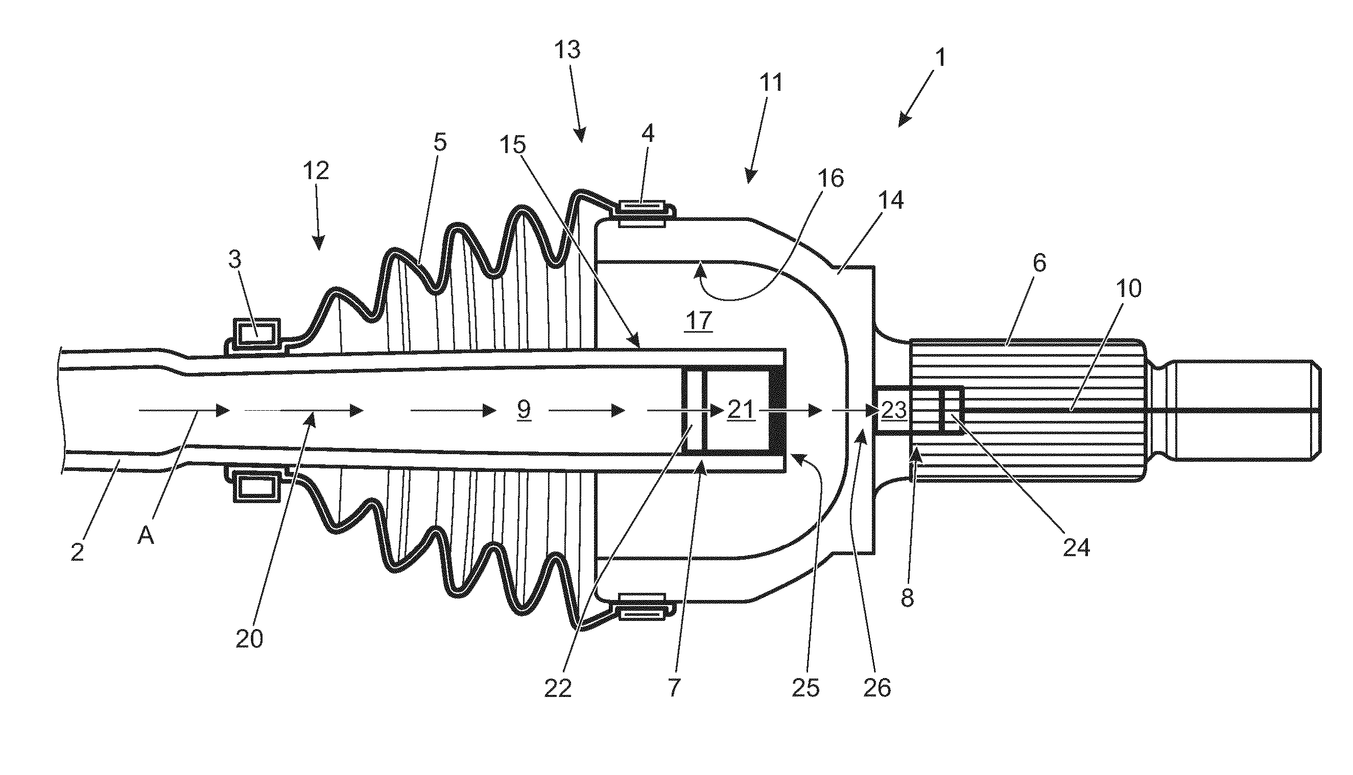
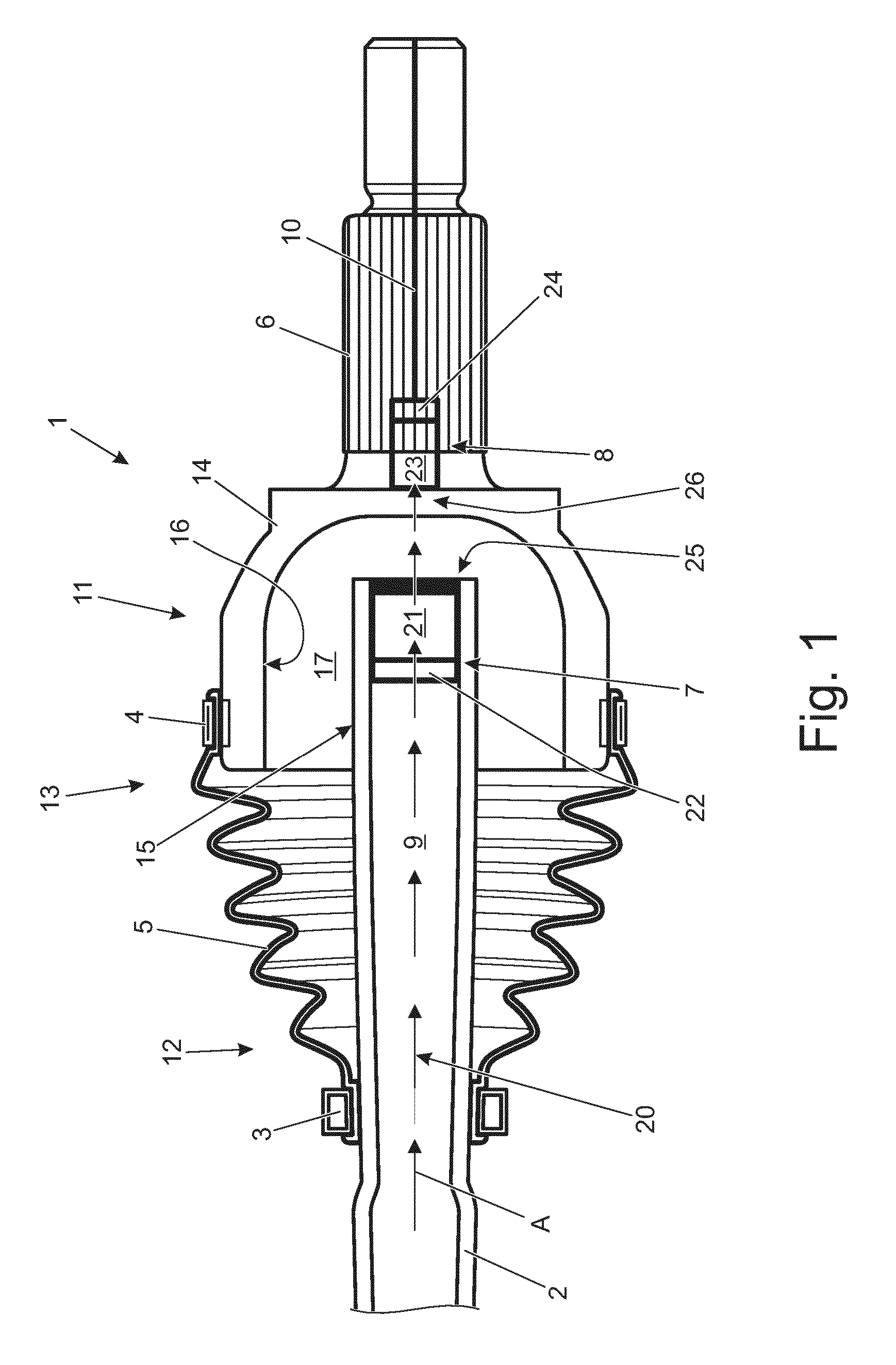
[0066]With reference to FIG. 1, a vehicle axle assembly 1 comprises: a driveshaft 2; first and second gaiter clamps 3, 4; a gaiter 5; a wheel stub axle 6; and first and second air filters 7, 8. The driveshaft 2 is a hollow shaft having a first internal conduit 9 extending therethrough to allow internal passage of compressed air from a compressed air source (not shown) located on-board the vehicle (not shown). The stub axle 6 is also a hollow shaft, and a second internal conduit 10 extends therethrough to transfer compressed air towards a wheel (not shown). The CTIS, tyre and wheel are not shown in the drawings and are of the type described in the co-pending patent application number GB1313622.1 filed on 30 Jul. 2013, the contents of which are incorporated herein in their entirety by reference.

[0067]It will be appreciated that the driveshaft 2 and the wheel stub axle form a constant velocity (CV) joint 11, although the internal parts of the CV joint 11 are not shown in FIG. 1 for cla...


PUM

PropertyMeasurementUnit
Thicknessaaaaaaaaaa
Oleophobicityaaaaaaaaaa

Abstract

A filter device (7, 8) for a conduit (9, 10) comprises a gas-permeable pre-filter element (21, 23) and a gas-permeable, liquid-impermeable filter element (22, 24). The filter device (7, 8) is configured to be fluidly coupled to a conduit (9, 10) such that a gas can be caused to flow, in sequence, through the pre-filter element (21, 23), the filter element (22, 24) and then the conduit (9, 10). Such a filter device (7, 8) can for example be used in each of a vehicle hollow driveshaft (2) and a hollow wheel stub axle (6) forming a CV joint (11) having a compressed air supply line which passes therethrough, as is the case in some central tyre inflation systems (CTISs). Thus, compressed air can be supplied via said air supply line without the need for an additional fluid transfer device fluidly connecting the driveshaft and the stub axle's conduits (9, 10).

Description

TECHNICAL FIELD[0001]The present disclosure relates to a filter device for a conduit. In particular, but not exclusively, aspects of the present invention relate to a filter device for a conduit of a central tyre inflation system (CTIS) air supply line; to a CTIS air supply line portion; to a hollow vehicle axle; to an articulated joint; to a CTIS; to a vehicle; and to a gas supply line portion.BACKGROUND OF THE INVENTION[0002]The present invention was conceived in the context of on-board central tyre inflation systems (CTISs) for land based vehicles. CTISs were originally developed for military applications, in particular for military applications concerning off-road military wheeled trucks and trailers. However, CTISs are nowadays incorporated into non-military vehicles such as specialist construction equipment and some agricultural vehicles.[0003]A CTIS typically comprises one or more compressed air sources located on-board the vehicle and connected to one or more tyres. Tyre pre...

Claims


Application Information

Patent Timeline
IPC IPC(8): B01D46/00B60C23/00
CPCB01D46/0023B60C23/00B01D46/0012B01D46/10B60C23/00336B01D46/62B01D53/228B01D69/02B01D71/32B01D71/36F16J3/041
Inventor DUNNING, EMMA-CLAIREHOARE, EDWARDLAANEMETS, LAURDODU, MAELLE
Owner JAGUAR LAND ROVER LTD
Why Eureka
Try Eureka