Supercharge Your Innovation With Domain-Expert AI Agents!

Deoiler debris baffle

Active Publication Date: 2016-07-21
RAYTHEON TECH CORP
View PDF1 Cites 9 Cited by
  • Summary
  • Abstract
  • Description
  • Claims
  • Application Information

AI Technical Summary

Benefits of technology

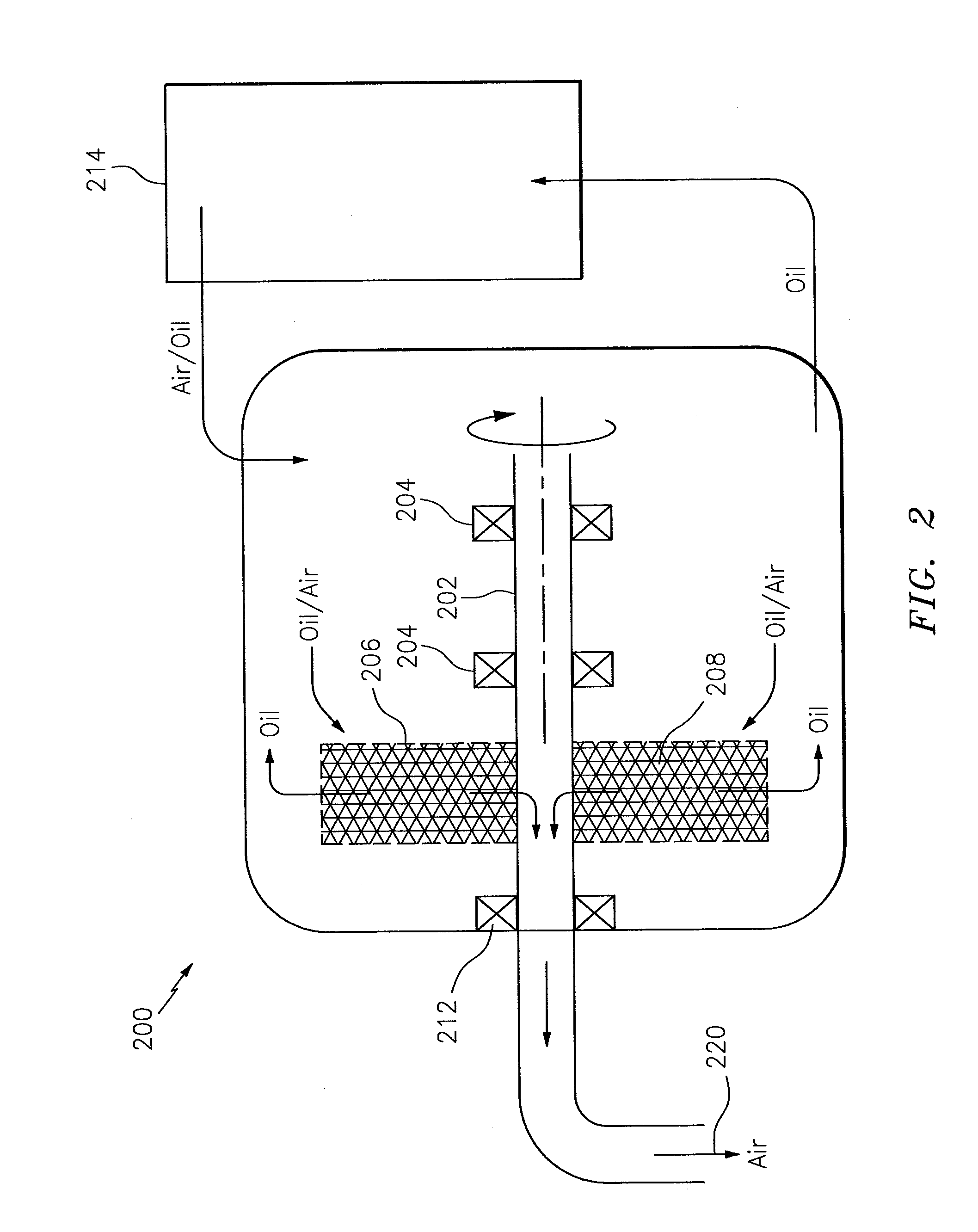
The patent describes a system that separates oil from air in an engine of an aircraft. The system includes a deoiler and a baffle to prevent debris from entering the deoiler. The separated oil is sent to an oil tank, while the separated air is sent to an overboard vent system. The system also includes a rotating shaft and bearings to support the shaft. The baffle is stationary and is made of porous or mesh material that captures the mixture of air and oil. The baffle has small pores that prevent bearing distress events.

Problems solved by technology

A deoiler, which is a device which separates oil from a breather air stream prior to venting the air overboard, may be contaminated by debris included in an oil flow entering the deoiler.

Method used


Image

  • Deoiler debris baffle
  • Deoiler debris baffle
  • Deoiler debris baffle

Examples


Embodiment Construction

[0008]It is noted that various connections are set forth between elements in the following description and in the drawings (the contents of which are included in this disclosure by way of reference). It is noted that these connections are general and, unless specified otherwise, may be direct or indirect and that this specification is not intended to be limiting in this respect. A coupling between two or more entities may refer to a direct connection or an indirect connection. An indirect connection may incorporate one or more intervening entities.

[0009]In accordance with various aspects of the disclosure, apparatuses, systems and methods are described for providing a deoiler debris baffle. The baffle may be used to prevent debris from entering a deoiler.

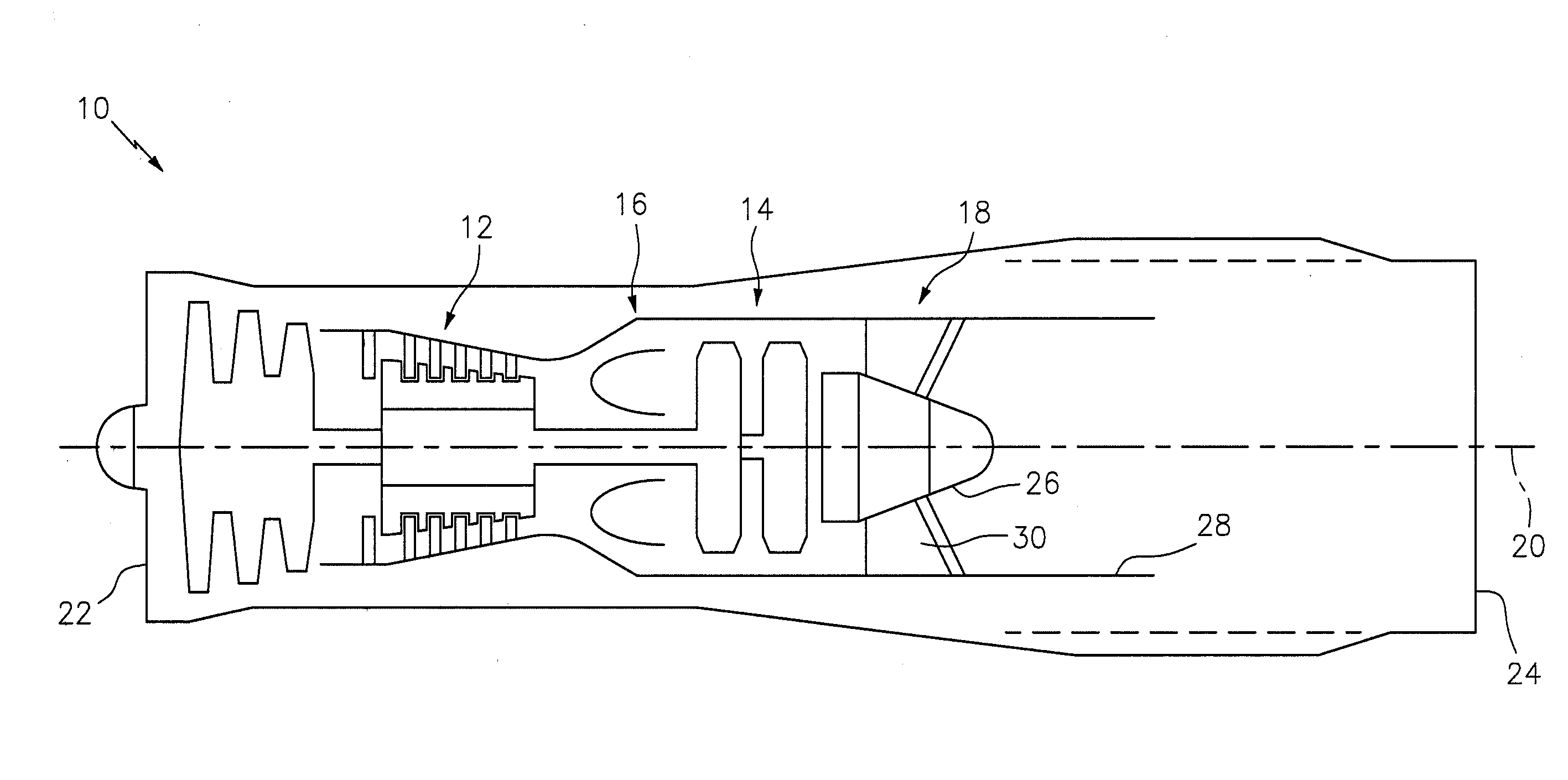
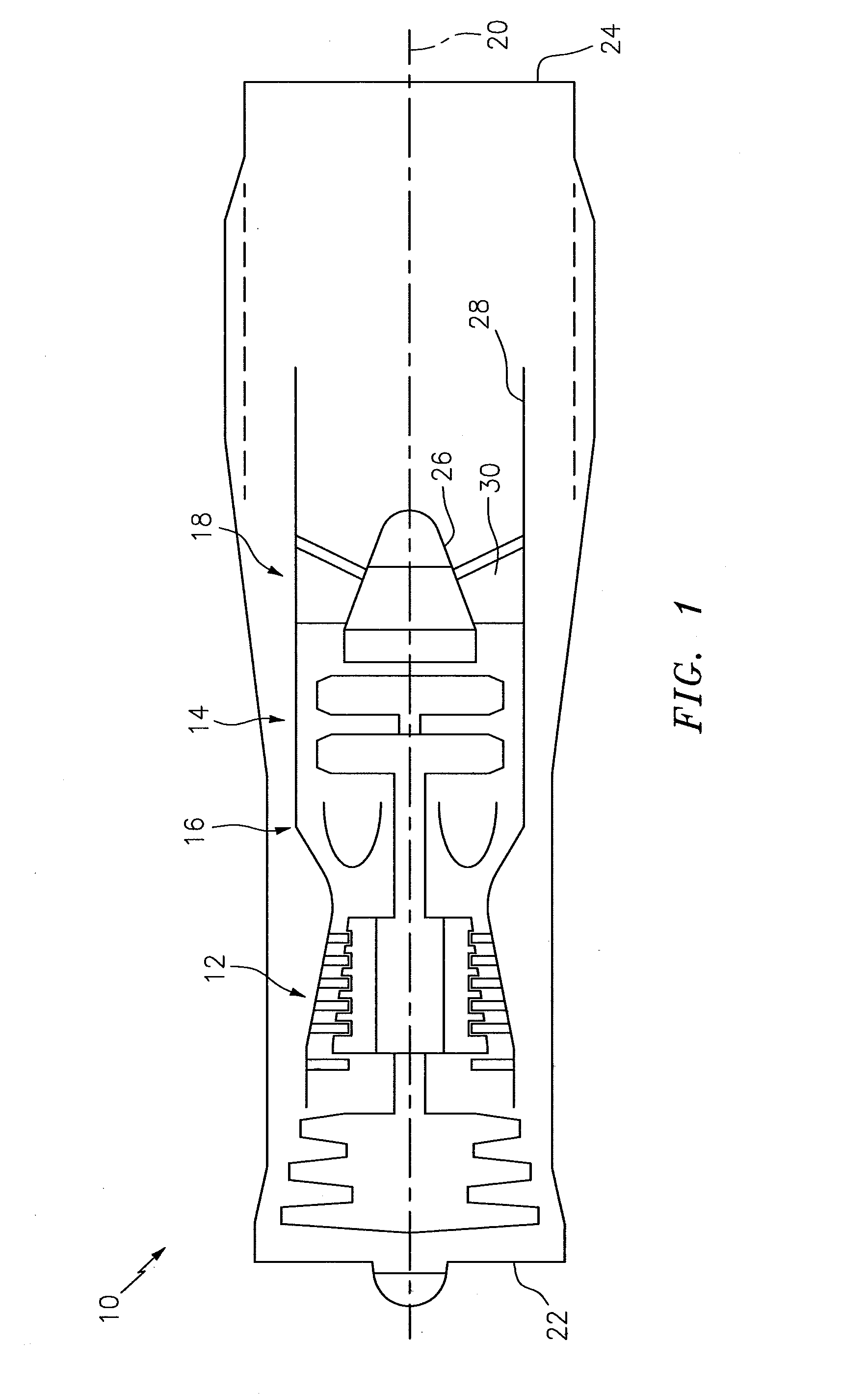
[0010]Aspects of the disclosure may be applied in connection with an aircraft, or portion thereof. For example, aspects of the disclosure may be applied in connection with a gas turbine engine. FIG. 1 is a side-sectional illustratio...


PUM

PropertyMeasurementUnit
Dimensionaaaaaaaaaa
Threshold limitaaaaaaaaaa

Abstract

Aspects of the disclosure are directed to a system associated with an engine of an aircraft, comprising: a deoiler configured to receive a mixture of air and oil at an input of the deoiler and separate the air from the oil, and a baffle coupled to the input of the deoiler and configured to prevent debris that is larger than a threshold from entering the deoiler.

Description

BACKGROUND[0001]Debris in a closed lubrication system must be removed from the system to avoid impact to other components and / or detection by debris monitors, chip collectors, oil filters, etc. A deoiler, which is a device which separates oil from a breather air stream prior to venting the air overboard, may be contaminated by debris included in an oil flow entering the deoiler. It is possible for the debris to reside on a surface of the deoiler or within the deoiler until a later time when the debris can work free to re-contaminate an otherwise clean oil system.BRIEF SUMMARY[0002]The following presents a simplified summary in order to provide a basic understanding of some aspects of the disclosure. The summary is not an extensive overview of the disclosure. It is neither intended to identify key or critical elements of the disclosure nor to delineate the scope of the disclosure. The following summary merely presents some concepts of the disclosure in a simplified form as a prelude ...

Claims


Application Information

Patent Timeline
IPC IPC(8): F01D25/18F01M13/04B01D46/00
CPCF01D25/18B01D46/0023F01M2013/0433F05D2230/72F01M2013/0422F01M13/04B01D45/14F05D2260/609F05D2260/607Y02T50/60B04B2005/125B04B5/12B01D46/62
Inventor CRAIG, COLIN D.ORSINI, MATTHEW J.
Owner RAYTHEON TECH CORP
Features
  • R&D
  • Intellectual Property
  • Life Sciences
  • Materials
  • Tech Scout
  • Unparalleled Data Quality
  • Higher Quality Content
  • 60% Fewer Hallucinations
Learn More