System and method for spinal fusion

a spinal fusion and system technology, applied in the field of spinal fusion systems and procedures, can solve the problems of no such method proposed

Inactive Publication Date: 2016-08-04
YUE JAMES J
View PDF6 Cites 6 Cited by
  • Summary
  • Abstract
  • Description
  • Claims
  • Application Information

AI Technical Summary

Benefits of technology

[0009]Provided is a spinal fusion apparatus comprising a first screw assembly configured to be inserted into a first lateral mass and second screw assembly configured to be inserted into a second lateral mass, wherein one of the first screw assembly and the seco

Problems solved by technology

However, to date, no such

Method used


Image

  • System and method for spinal fusion
  • System and method for spinal fusion
  • System and method for spinal fusion

Examples


Embodiment Construction

[0053]The matters defined in the description such as a detailed construction and elements are provided to assist in a comprehensive understanding of the embodiments of the invention and are merely exemplary. Accordingly, those of ordinary skill in the art will recognize that various changes and modifications of the embodiments described herein can be made without departing from the scope and spirit of the invention. Also, descriptions of well-known functions and constructions are omitted for clarity and conciseness.

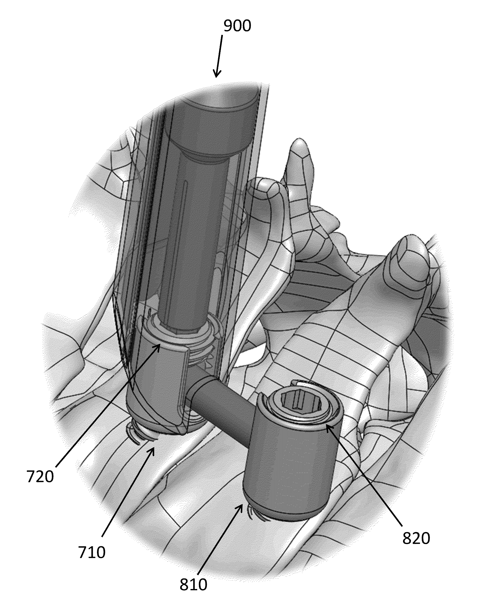
[0054]Spinal fusion devices of exemplary embodiments set forth herein are implants including a combination screw and flip-rod (a screw-rod). The screw-rod implant comprises a screw with a mobile tulip. Within the tulip, there exists a mobile housing in which a rod having a semi-spherical coupling can fit. One end of the rod has a non-round shape which permits the one end of the rod to sit in a male or female receptacle for turning a threaded shaft of the screw. The other ...


PUM


Abstract

A system for spinal fusion according to exemplary aspects involves a first screw and a second screw to be inserted into a lateral mass, wherein one of the first screw and the second screw comprises a rod configured to form a pivot joint with a tulip of one of the screws. A tulip of the first screw and a tulip of the second screw each comprise at least one slot configured to mate with the rod to thereby connect the first screw and the second screw. A method of exemplary aspects involves implanting a first screw and a second screw and connecting the screw by lowering a rod of one of the screws into a tulip of the other screw.

Description

CROSS-REFERENCE TO RELATED APPLICATION[0001]This application claims priority under 35 U.S.C. §119 to U.S. Provisional Application No. 62 / 111,902, filed on Feb. 4, 2015, the contents of which are herein incorporated by reference in their entirety.BACKGROUND OF THE INVENTION[0002]1. Field of the Invention[0003]The present invention relates to the field of spinal fusion devices and procedures, and more particularly, relates to a system and method for spinal fusion using a screw and rod device for joining two or more vertebral bodies by posterior cervical fusion.[0004]2. Description of the Related Art[0005]Spinal fusion is a surgical technique used to join two or more vertebrae. Fusing of the spine is used to eliminate pain caused by abnormal motion of the vertebrae by immobilizing the faulty vertebrae themselves, which is usually caused by degenerative conditions.[0006]Posterior cervical fusion is indicated for patients with numerous pathological conditions including traumatic and path...

Claims


Application Information

Patent Timeline
IPC IPC(8): A61B17/70A61B17/16A61B17/17A61B17/34
CPCA61B17/7032A61B17/3468A61B17/3472A61B17/7037A61B17/1757A61B17/7002A61B17/1671A61B17/7005A61B17/7082A61B17/7091A61B17/7076
Inventor YUE, JAMES J.
Owner YUE JAMES J
Why Eureka
Try Eureka