Image forming system, image forming apparatus, and skew correction method

a technology of image forming and skew correction, which is applied in the direction of electrographic process equipment, thin material processing, instruments, etc., can solve the problems of sheet jamming and productivity decline, and achieve the effect of suppressing productivity declin

Active Publication Date: 2016-08-18
KONICA MINOLTA INC
View PDF1 Cites 3 Cited by
  • Summary
  • Abstract
  • Description
  • Claims
  • Application Information

AI Technical Summary

Benefits of technology

[0010]An object of the present invention is to provide an image forming system, an image forming apparatus, and a skew correction method which can suppress deterioration of productivity when a toner image is formed on a long sheet.

Problems solved by technology

Incidentally, in the above image forming system, a sheet jam, in which a long sheet being conveyed on a sheet conveyance path of the long sheet is jammed during an image forming operation to form a toner image on the long sheet, may occur.
Thus, occurrence of a sheet jam causes a problem that productivity is deteriorated during suspending the image forming operation.
In the technique disclosed in JP 2012-116153 A, a process, in which a jammed part is removed and a continuous paper is reset after the jam occurs, is required, and which causes a problem similar to the above problem.

Method used


Image

  • Image forming system, image forming apparatus, and skew correction method
  • Image forming system, image forming apparatus, and skew correction method
  • Image forming system, image forming apparatus, and skew correction method

Examples


Embodiment Construction

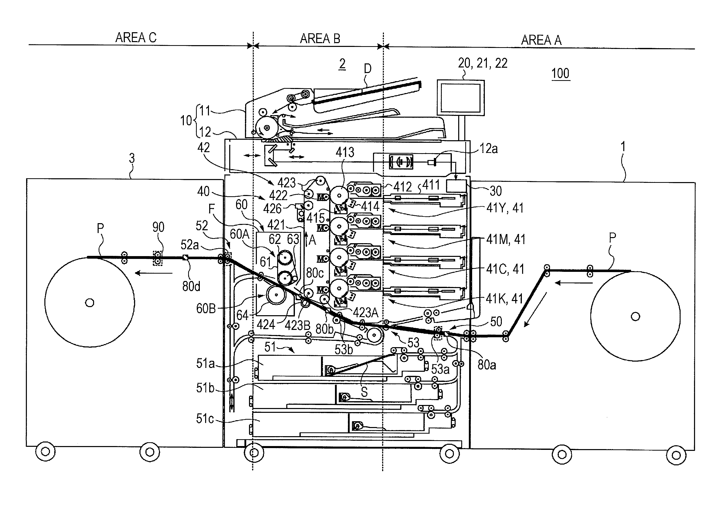
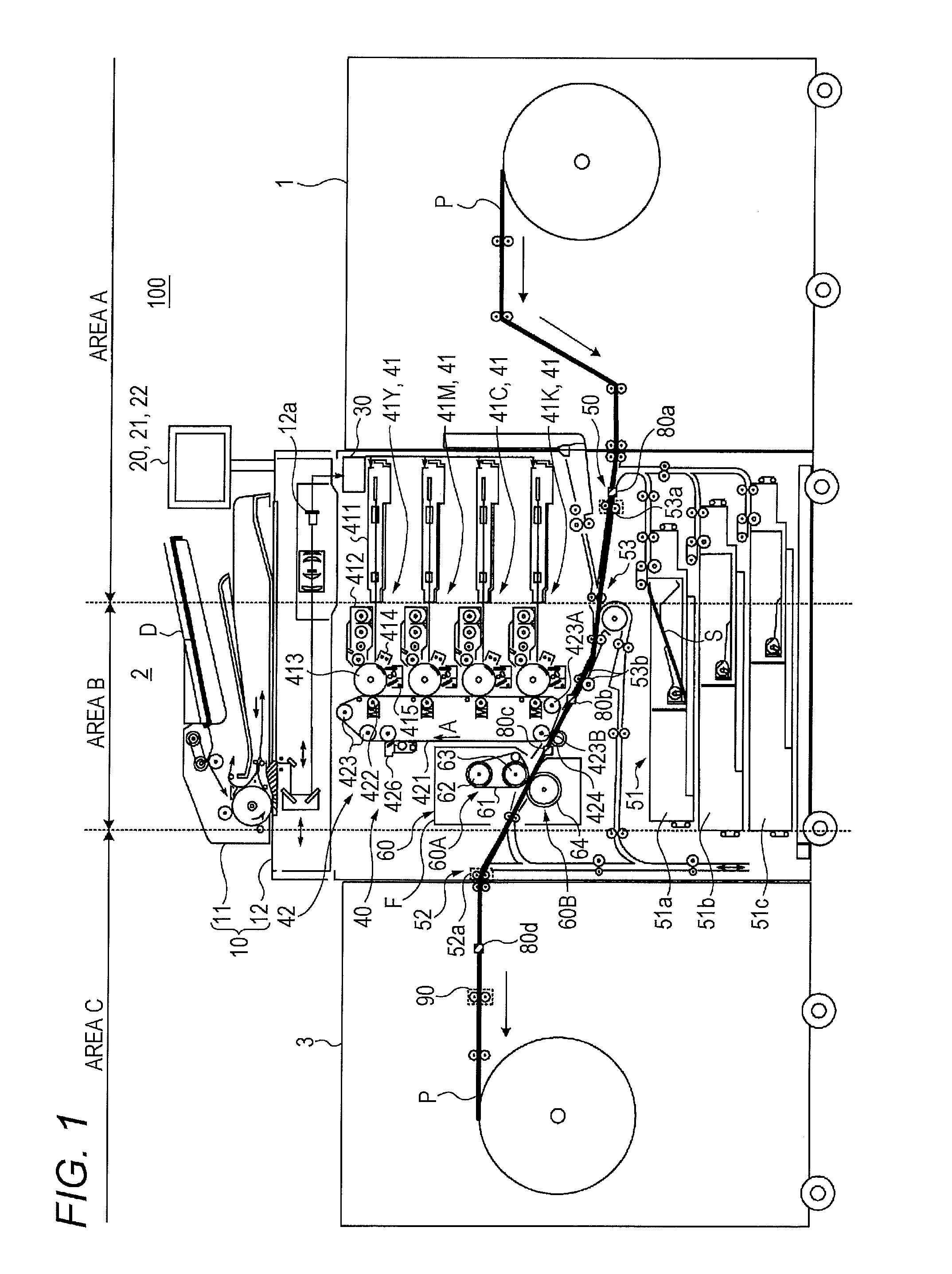
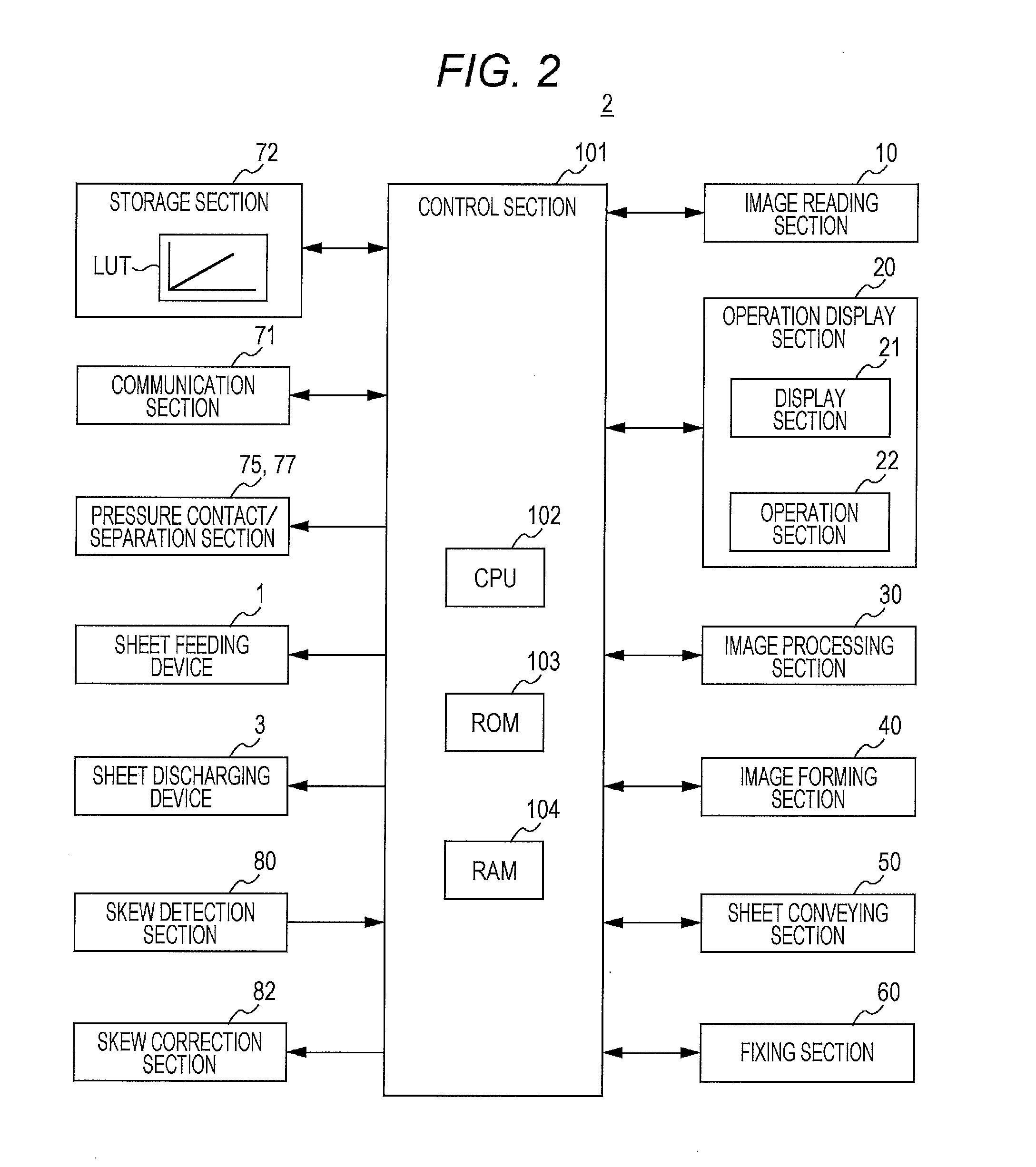
[0018]Hereinafter, an embodiment of the present invention will be described with reference to the drawings. However, the scope of the invention is not limited to the illustrated examples. FIG. 1 is a diagram schematically illustrating a configuration of an entire image forming system 100 according to the present embodiment. FIG. 2 illustrates a main part of a control system of an image forming apparatus 2 included in the image forming system 100 according to the present embodiment. The image forming system 100 uses, as a recording medium, a long sheet P indicated by a thick line in FIG. 1 or a sheet (also referred to as a cut sheet) S cut into a predetermined sheet size, and forms a toner image on the long sheet P or the sheet S. Here, the long sheet P is a sheet having a length longer than, for example, the main body width of the image forming apparatus 2 in the conveyance direction thereof.

[0019]As illustrated in FIG. 1, the image forming system 100 is constituted by connecting a ...


PUM

PropertyMeasurementUnit
sizeaaaaaaaaaa
diameteraaaaaaaaaa
tensionaaaaaaaaaa

Abstract

An image forming system includes: a sheet conveying section configured to convey a long sheet; an image forming/fixing section configured to execute an image forming/fixing operation to form and fix a toner image on the long sheet to be conveyed by the sheet conveying section; a skew detection section configured to detect a skew of the long sheet to be conveyed by the sheet conveying section; a skew correction section configured to execute a skew correction operation to correct the skew of the long sheet; and a control section configured to perform control to execute the skew correction operation when the skew has been detected in a first area where the skew correction operation does not affect the image forming/fixing operation, and perform control to execute the skew correction operation when the skew has been detected in a second area where the skew correction operation affects the image forming/fixing operation.

Description

[0001]The entire disclosure of Japanese Patent Application No. 2015-029670 filed on Feb. 18, 2015 including description, claims, drawings, and abstract are incorporated herein by reference in its entirety.BACKGROUND OF THE INVENTION[0002]1. Field of the Invention[0003]The present invention relates to an image forming system, an image forming apparatus, and a skew correction method.[0004]2. Description of the Related Art[0005]Commonly, an image forming apparatus using an electrophotographic process technology (such as a printer, a copying machine, and a facsimile) forms an electrostatic latent image by irradiating (exposing) a charged photoconductor with (to) laser light based on image data. Then, the electrostatic latent image is visualized by supplying toner from a developing device to a photoconductor drum on which the electrostatic latent image is formed, and a toner image is formed accordingly. Thereafter, the toner image is directly or indirectly transferred to a sheet, and the...

Claims


Application Information

Patent Timeline
Patent Type & Authority Applications(United States)
IPC IPC(8): B65H23/032B65H20/02
CPCB65H20/02B65H23/032B65H23/038B65H2301/331B65H2404/15212B65H2515/314B65H2553/41B65H2701/1315B65H2701/1842B65H2801/06G03G15/55G03G15/6517G03G15/652G03G15/6567G03G2215/00561
Inventor NAKAMURA, ATSUSHI
Owner KONICA MINOLTA INC
Why Eureka
Try Eureka