
Lidar assisted focusing device

a focusing device and assisted focusing technology, applied in the field of optics, can solve the problems of many focusing systems limited to a field of view less than one degr

Active Publication Date: 2016-08-25
REDROCK MICROSYST
View PDF5 Cites 19 Cited by
  • Summary
  • Abstract
  • Description
  • Claims
  • Application Information

AI Technical Summary

Benefits of technology

The present invention provides a focusing device for a camera that uses LIDAR data to determine a focus setting and automatically sends it to the camera interface to drive the lens to focus on a target selection. Additionally, this invention provides a focus / pan / tilt device that uses LIDAR data to automatically determine a focus, pan, and tilt setting and sends it to the camera interface to track a movement of a target. These technical effects make it easier for users to capture high-quality images and videos with their cameras.

Problems solved by technology

Many focusing systems are limited to a field of view of less than one degree.
Moreover, people must often rely only on the auto focusing system integrated into their camera.

Method used


Image

  • Lidar assisted focusing device
  • Lidar assisted focusing device
  • Lidar assisted focusing device

Examples


Embodiment Construction

[0012]While the making and using of various embodiments of the present invention are discussed in detail below, it should be appreciated that the present invention provides many applicable inventive concepts that can be embodied in a wide variety of specific contexts. The specific embodiments discussed herein are merely illustrative of specific ways to make and use the invention and do not delimit the scope of the invention. For example, the embodiments described below relate to focusing a camera lens.

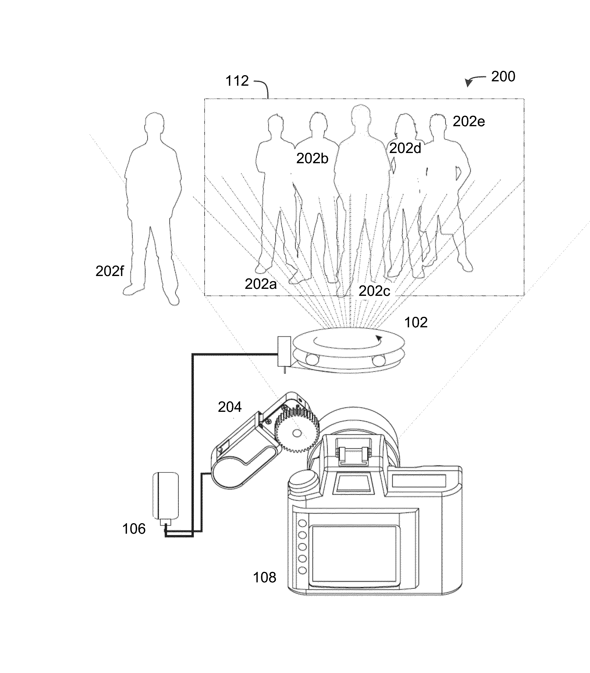
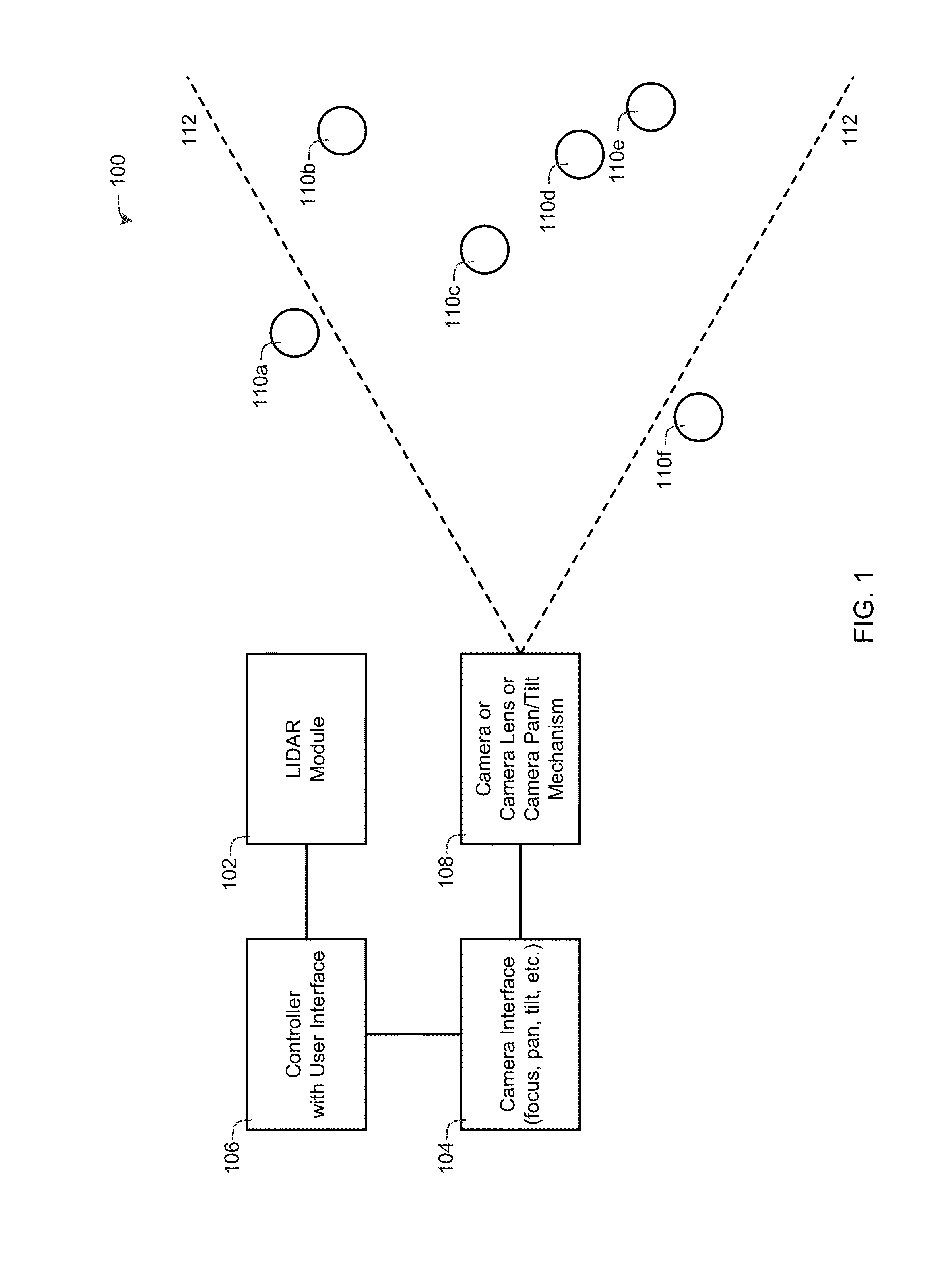
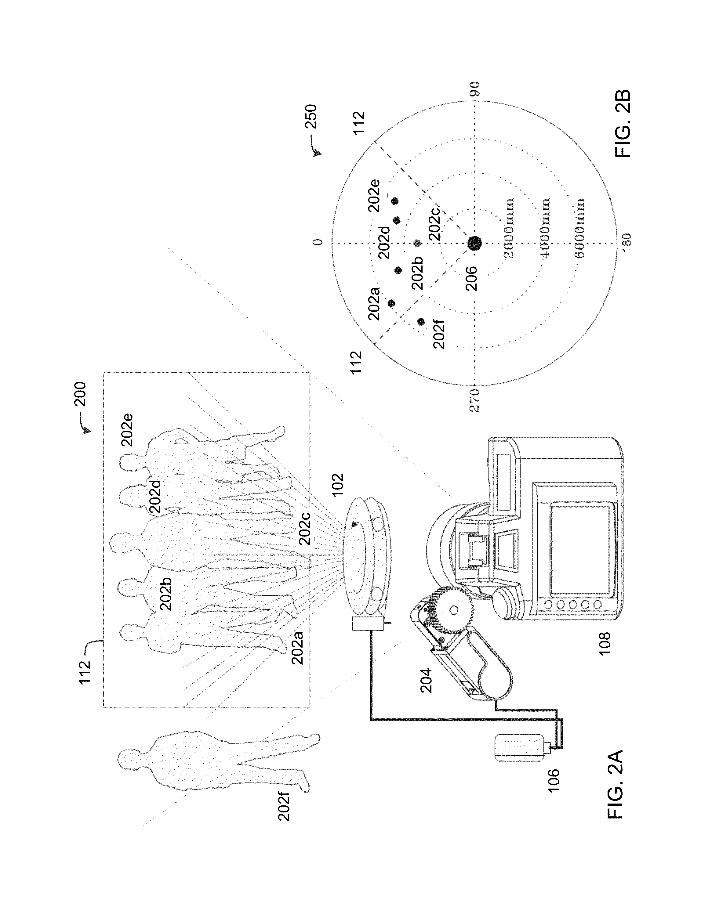
[0013]Now referring to FIG. 1, a block diagram depicting a focusing device 100 in accordance one embodiment of the present invention is shown. The focusing device 100 includes a LIDAR module 102, one or more camera interfaces 104 and a controller 106 communicably coupled to the LIDAR module 102 and the one or more camera interfaces 104. The LIDAR module 102 is a rotating laser distance scanner capable of scanning up to 360 degrees of data. Typically, the LIDAR module 102 is mounted to ...


PUM


Abstract

A focusing device for a camera having a lens includes a LIDAR module, a camera interface and a controller communicably coupled to the LIDAR module and the camera interface. The controller receives data from the LIDAR module, displays one or more targets using the data from the LIDAR module via a user interface, receives a target selection via the user interface, determines a focus setting using the LIDAR data, the target selection and a camera operational data, and sends the focus setting to the camera interface. The camera interface receives the focus setting and drives the lens of the camera to focus on the target selection using the focus setting.

Description

CROSS-REFERENCE TO RELATED APPLICATIONS[0001]This non-provisional Patent Application claims priority to U.S. Provisional Patent Application Ser. No. 62 / 120,095, filed Feb. 24, 2015, entitled “LIDAR Assisted Focusing System,” the contents of which is incorporated by reference herein in its entirety.INCORPORATION-BY-REFERENCE OF MATERIALS FILED ON COMPACT DISC[0002]None.TECHNICAL FIELD OF THE INVENTION[0003]The present invention relates in general to optics and more specifically to a LIDAR assisted focusing device.STATEMENT OF FEDERALLY FUNDED RESEARCH[0004]None.BACKGROUND OF THE INVENTION[0005]Without limiting the scope of the invention, its background is described in connection with camera focusing systems. Many focusing systems are limited to a field of view of less than one degree. Moreover, people must often rely only on the auto focusing system integrated into their camera.SUMMARY OF THE INVENTION[0006]One embodiment of the present invention provides a focusing device for a came...

Claims


Application Information

Patent Timeline
Patent Type & Authority Applications(United States)
IPC IPC(8): H04N5/232H04N5/225
CPCH04N5/23216H04N5/23293H04N5/2259H04N5/23212G01S17/08G01S17/42G01S17/88G01S7/4813G02B7/40H04N23/675H04N23/61H04N23/695H04N23/62
Inventor HURD, JAMES D.
Owner REDROCK MICROSYST
Learn More