Tube in cross-flow conduit heat exchanger

a heat exchanger and cross-flow technology, applied in indirect heat exchangers, machines/engines, lighting and heating apparatus, etc., can solve the problems of insufficient pressure for bypassing air, insufficient pressure for cooled bleed air to reach the user application, and many limitations on the design of the heat exchanger system

Active Publication Date: 2016-09-15
GENERAL ELECTRIC CO
View PDF8 Cites 28 Cited by
  • Summary
  • Abstract
  • Description
  • Claims
  • Application Information

AI Technical Summary

Benefits of technology

[0006]Aspects and advantages of the invention will be set forth in part in the following description, or may be obvious from the description, or may be learned through practice of the invention.

Problems solved by technology

There are several limitations on the design of the heat exchanger system that exchanges heat between the bleed air and the bypass air.
The inlet manifold that brings the hot bleed air to the heat exchanger, the heat exchanger itself, and the outlet manifold that transports the cooled bleed air away from the heat exchanger cannot together impose too great a pressure drop, or the cooled bleed air that reaches the user application will have insufficient pressure to perform properly.
The heat exchanger itself cannot impose too great a pressure drop on the engine bypass air flowing through the fan duct, or the bypass air will have insufficient pressure to perform properly.
Weight and size also impose tight limitations.
The heat exchanger system also cannot significantly increase the envelope size of the gas turbine engine, and desirably is as small as possible to leave installation space for other aircraft systems.
These dimensional changes must be accounted for in the heat exchanger structure, or otherwise the resulting stresses and strains would lead to premature failure of the heat exchanger unit.

Method used


Image

  • Tube in cross-flow conduit heat exchanger
  • Tube in cross-flow conduit heat exchanger
  • Tube in cross-flow conduit heat exchanger

Examples


Embodiment Construction

[0032]Reference now will be made in detail to embodiments of the invention, one or more examples of which are illustrated in the drawings. Each example is provided by way of explanation of the invention, not limitation of the invention. In fact, it will be apparent to those skilled in the art that various modifications and variations can be made in the present invention without departing from the scope or spirit of the invention. For instance, features illustrated or described as part of one embodiment can be used with another embodiment to yield a still further embodiment. Thus, it is intended that the present invention covers such modifications and variations as come within the scope of the appended claims and their equivalents.

[0033]As used herein, the terms “first”, “second”, and “third” may be used interchangeably to distinguish one component from another and are not intended to signify location or importance of the individual components.

[0034]The terms “upstream” and “downstre...


PUM


Abstract

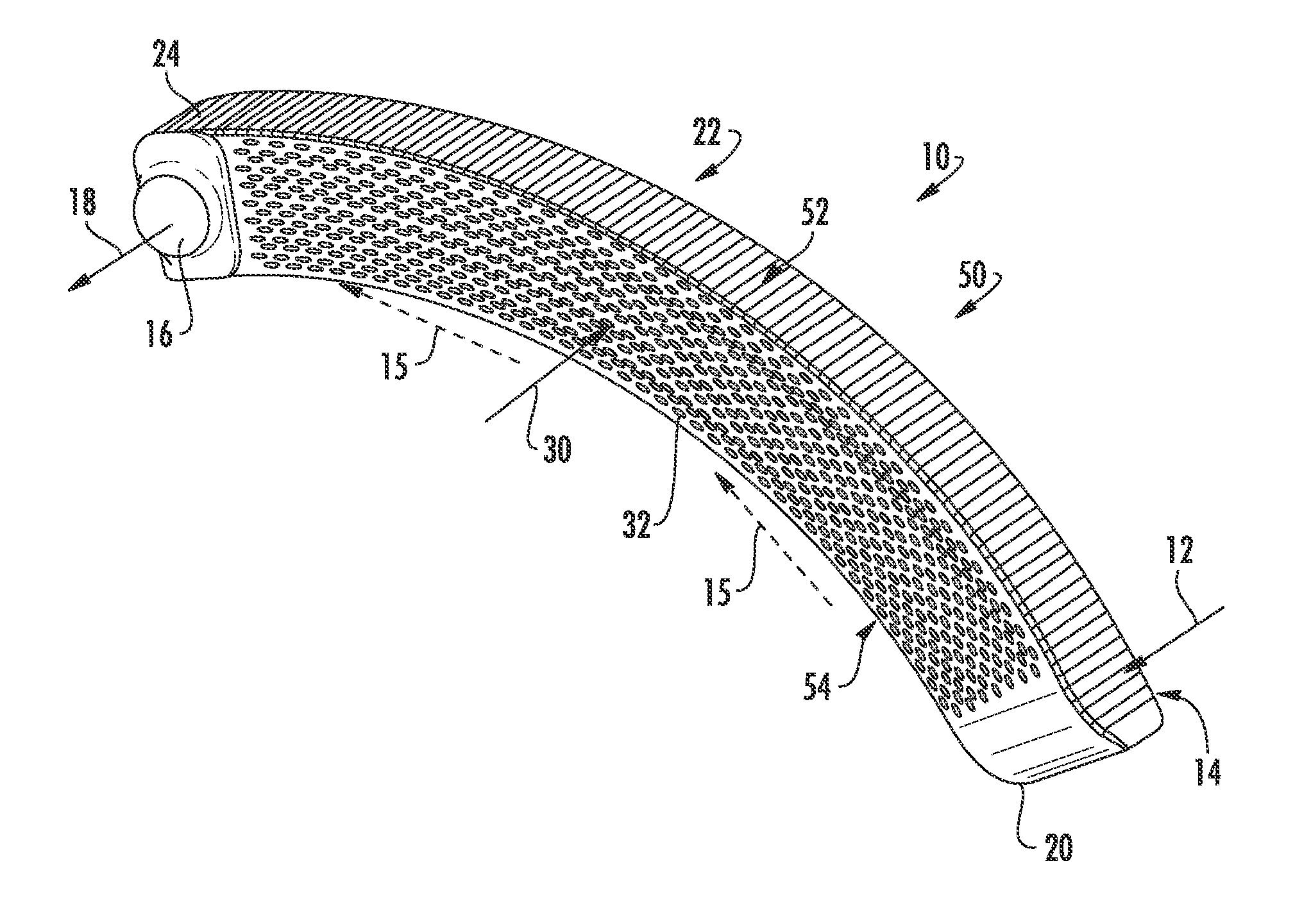
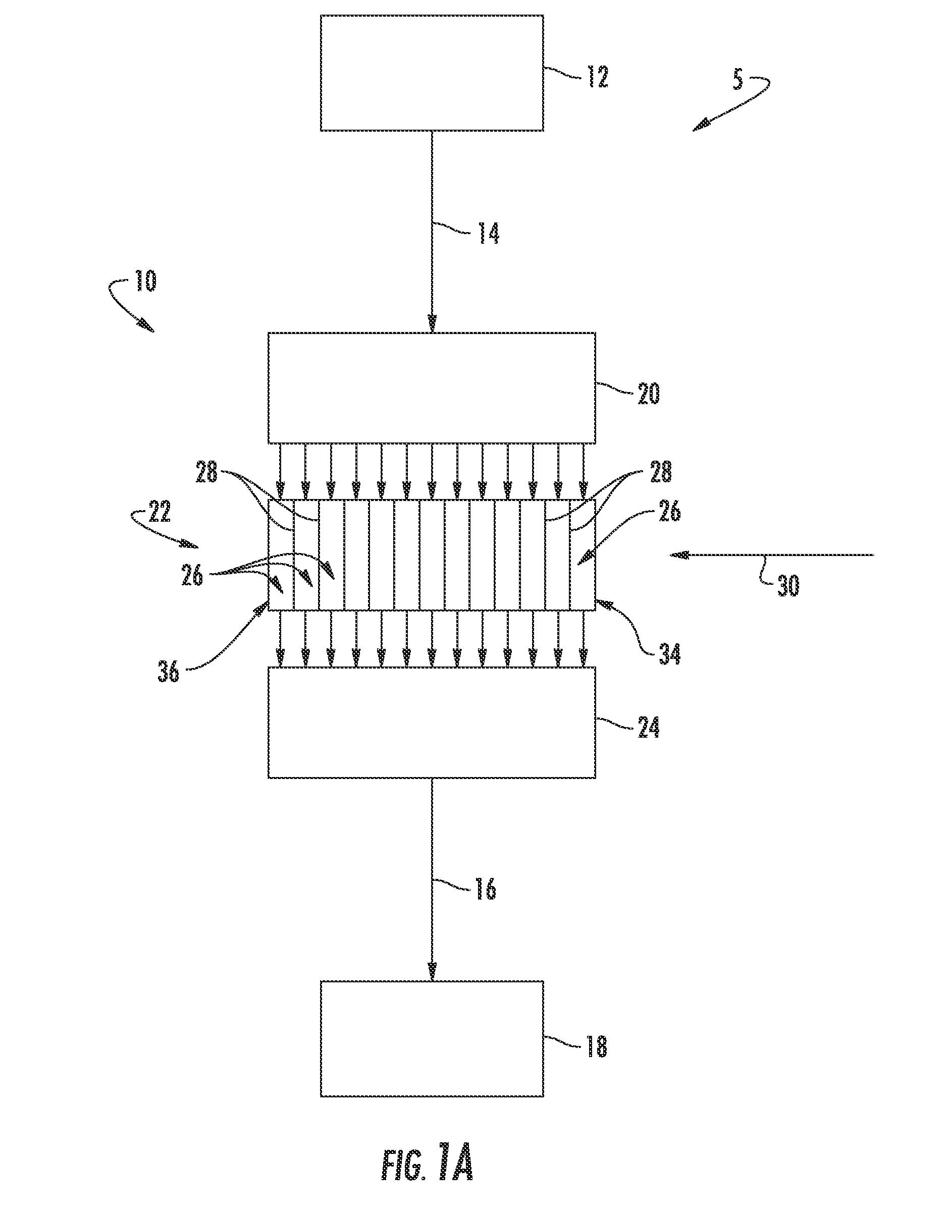
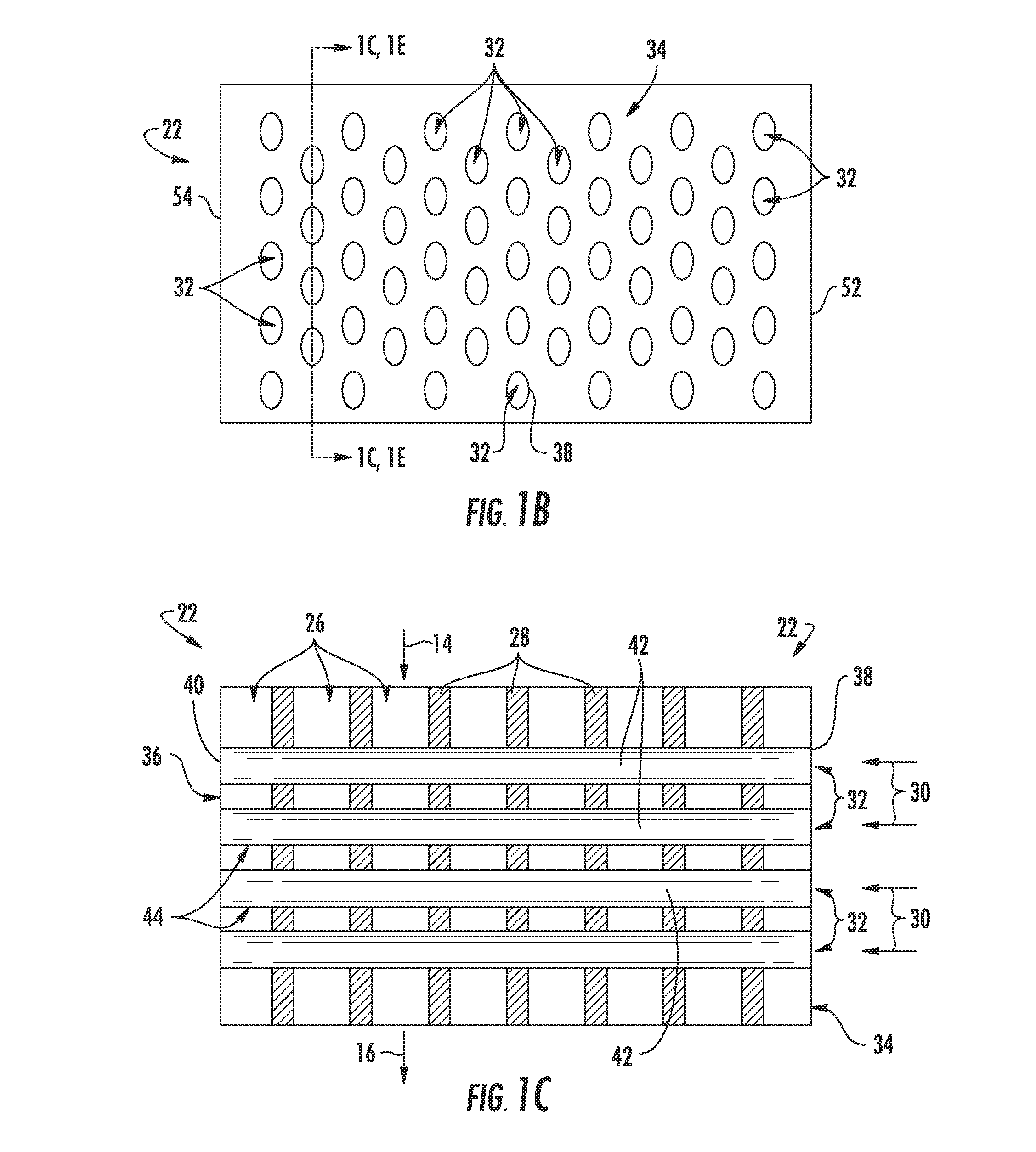
A heat exchanger that includes an input cavity defined by inlet cavity walls; a heat exchanger portion in fluid communication with the input cavity and defined between a first side and a second side, and wherein a plurality of baffles are positioned within the heat exchanger portion; and an outlet cavity in fluid communication with the heat exchanger portion and defined by outlet cavity walls. The heat exchanger portion comprises: a plurality of first fluid paths defined between the baffles and extending from the input cavity to the outlet cavity, and a plurality of tubes extending through the heat exchanger portion from the first side to the second side. Each tube extends through the baffles so as to define a second fluid path through the heat exchanger portion. Heat exchanger systems are also generally provided, along with methods for cooling a hot fluid input with a heat exchanger.

Description

FIELD OF THE INVENTION[0001]The present invention relates to a heat exchanger system that uses a cooling fluid flowing in tubes with the hot fluid path flowing through a conduit and routed in cross-flow over the exterior of the tubes.BACKGROUND OF THE INVENTION[0002]In an aircraft design, a continuous flow of hot air is bled from one part of a gas turbine engine, cooled, and provided to a specific user application. A heat exchanger system may be used to cool the hot bleed air.[0003]The preferred medium for cooling hot bleed air is engine bypass air that flows through the gas turbine fan duct. There are several limitations on the design of the heat exchanger system that exchanges heat between the bleed air and the bypass air. The inlet manifold that brings the hot bleed air to the heat exchanger, the heat exchanger itself, and the outlet manifold that transports the cooled bleed air away from the heat exchanger cannot together impose too great a pressure drop, or the cooled bleed air...

Claims


Application Information

Patent Timeline
Patent Type & Authority Applications(United States)
IPC IPC(8): F28D1/02F28D1/053
CPCF28D1/05375F28D1/0233F02C7/12F28D21/00F28F9/00F28F13/12F28D2021/004F28F2225/08F01D25/12F28D7/163F28F1/006F28D2021/0021F28F2009/226F28F2225/02Y02T50/60
Inventor KUPISZEWSKI, THOMASRAMBO, JEFFREY DOUGLASBONAR, JAMES F.WOLFE, JARED
Owner GENERAL ELECTRIC CO
Why Eureka
Try Eureka