
Electronic Device, Time Correction Method, and Time Correction Program

a technology of electronic devices and time correction methods, applied in the direction of electric winding, instruments, horology, etc., can solve the problems of difficult time correction, inability to determine whether the first or the second hands correction mode is set, etc., and achieve the effect of easy time setting

Active Publication Date: 2016-09-15
SEIKO EPSON CORP
View PDF4 Cites 30 Cited by
  • Summary
  • Abstract
  • Description
  • Claims
  • Application Information

AI Technical Summary

Benefits of technology

The patent is about an electronic device, a method, and a program that can display multiple times and easily set the time. The technical effect of the patent is to enable easy and accurate time correction.

Problems solved by technology

However, if the user does not remember the relationship between the stop position of the crown and the time correction mode when pulling the crown out to adjust the first hands or the second hands of the electronic timepiece described in JP-A-2009-8504, determining whether the first hands correction mode or the second hands correction mode is set is not easy.
Correcting the desired displayed time is therefore difficult.

Method used


Image

  • Electronic Device, Time Correction Method, and Time Correction Program
  • Electronic Device, Time Correction Method, and Time Correction Program
  • Electronic Device, Time Correction Method, and Time Correction Program

Examples


embodiment 1

Effect of Embodiment 1

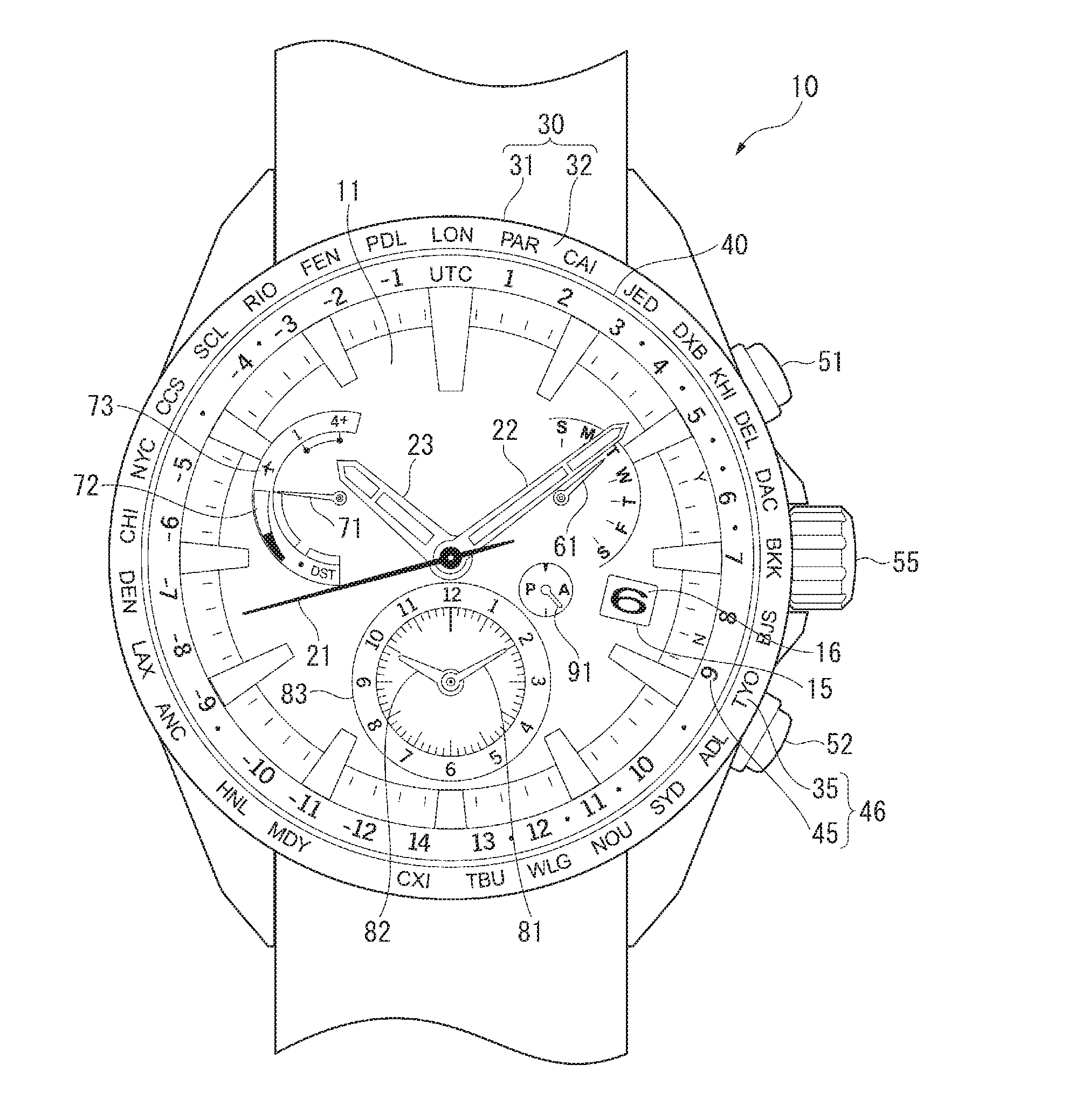
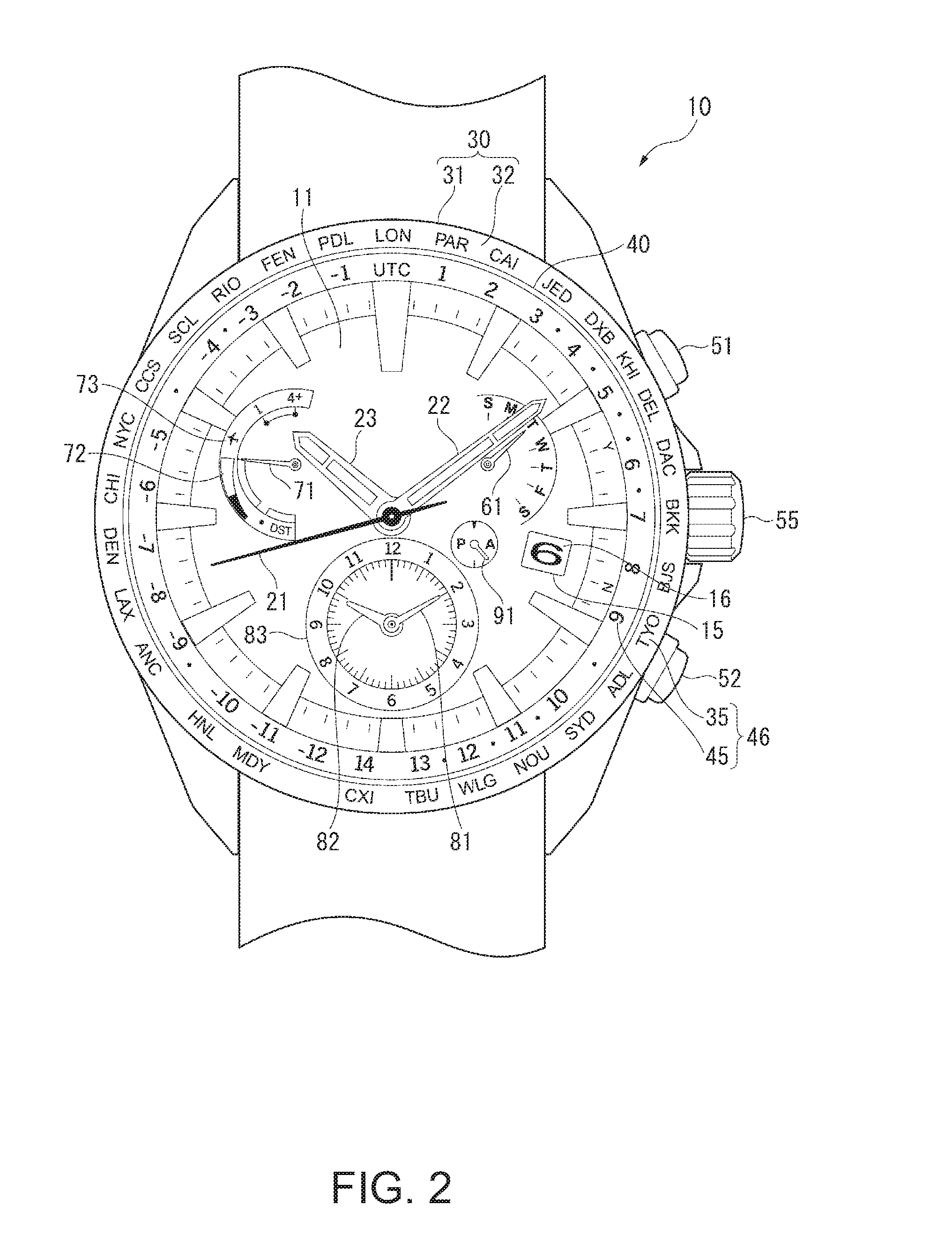
[0209]When the crown 55 is moved to the first stop to enter the time correction mode and the first time correction mode is set, the user knows that the second time correction mode is not set by checking the hand 61 because the hand 61 points to a position other than the hands 81, 82. In other words, the user can know that the first time correction mode is set. Because the hand 61 points to the hands 81, 82 when the second time correction mode is set, the user can easily know that the second time correction mode is set by checking the position of the hand 61. The desired time can therefore be easily corrected.

[0210]Because the hand 61 indicates the day when in the normal time display mode, there is no need to provide the electronic timepiece 10 with a separate hand to indicate the day, and the number of hands used on the electronic timepiece 10 can be reduced.

[0211]Furthermore, because the hand 61 continues to indicate the day of the first time when the first ti...

embodiment 2

Effect of Embodiment 2

[0225]The second embodiment has the same effect as the first embodiment. That is, if the first time correction mode is set, the hand 71 points to a different position than the hands 81, 82. The user can therefore know if the first time correction mode is set by reading the hand 71. Furthermore, because the hand 71 points to the hands 81, 82 if the second time correction mode is set, the user can easily know if the second time correction mode is set by reading the hand 71. Setting the time is therefore simple. The second embodiment also has the following effect.

[0226]When the user performs the second time selection operation, the user can know by reading the hand 71 that the second time correction mode was set, and can then know the DST setting of the second time by reading the hand 71 after it moves because the indication time has past or the stop indication operation was performed.

[0227]As a result, there is no need to provide the electronic timepiece 10A with...


PUM


Abstract

An electronic device has a first hand that displays a first time; a secondhand that displays a second time; an indicator hand; a detection device that outputs a first time selection signal when it detects a first time selection operation of an input device, and outputs a second time selection signal when it detects a second time selection operation of the input device; a mode setter that sets a first time correction mode to correct the first time when the first time selection signal is received, and sets a second time correction mode to correct the second time when the second time selection signal is received; and a display controller that points the indicator hand to a position other than that of the second hand when the first time correction mode is set, and points the indicator hand to the second hand when the second time correction mode is set.

Description

CROSS-REFERENCE TO RELATED APPLICATION(S)[0001]This application claims priority under 35 U.S.C. §119 on Japanese Patent Application No. 2015-046364, filed Mar. 9, 2015. The content of this priority application is incorporated by reference in its entirety.BACKGROUND[0002]1. Technical Field[0003]The present invention relates to an electronic device, a time correction method, and a time correction program.[0004]2. Related Art[0005]Electronic timepieces that have two sets of hour, minute, and second hands for displaying two different times are known from the literature. See, for example, JP-A-2009-8504.[0006]The electronic timepiece described in JP-A-2009-8504 has first hands including a first minute hand and a first hour hand disposed to a pivot in the center of the dial, and second hands including a second minute hand and a second hour hand disposed to a pivot located at a position offset toward 6:00 from the center pivot of the dial. When the crown is pulled out to the first stop, th...

Claims


Application Information

Patent Timeline
IPC IPC(8): G04B27/00G04B47/00
CPCG04B47/003G04B27/002G04R20/02G04C17/00G04G9/0064G04G9/0076G04R20/00G04B19/22G04C3/14
Inventor AKIYAMA, TOSHIKAZU
Owner SEIKO EPSON CORP
Learn More