Pump including a moving member provided with a central duct and a diaphragm having engagement means bearing against said central duct, and a receptacle fitted therewith

a technology of diaphragm and moving member, which is applied in the direction of piston pumps, positive displacement liquid engines, instruments, etc., can solve the problems of pushbutton jamming and known pump not providing full satisfaction, so as to reduce mechanical stress, facilitate diaphragm operation, and reduce mechanical stress

Inactive Publication Date: 2001-08-23
LOREAL SA
View PDF0 Cites 5 Cited by
  • Summary
  • Abstract
  • Description
  • Claims
  • Application Information

AI Technical Summary

Benefits of technology

0014] In the invention, the central portion of the diaphragm comes to bear against the central duct at a location that is remote from the end thereof, thereby reducing the mechanical stresses to which the end wall of the central portion of the diaphragm is subjected.
0015] In addition, because the end wall of the central portion of the diaphragm is subjected to less stress, it becomes easier to enable the diaphragm to perform its delivery valve function, i.e. to enable it to isolate the pump chamber from the opening(s) of the central duct while the volume of the pump chamber is increasing and substance is being sucked into the chamber. The bottom portion of the central portion of the diaphragm can deform more easily in a direction perpendicular to the direction in which the top portion of the central portion of the diaphragm is stretched because it is subjected to less axial stress, and this makes it easier to pass the substance that is to be dispensed.

Problems solved by technology

Nevertheless, that known pump does not provide full satisfaction.
In particular, the pump can be difficult to prime and under certain conditions the substance flows with difficulty between the central duct of the pushbutton and the diaphragm, thereby causing the pushbutton to jam.

Method used


Image

  • Pump including a moving member provided with a central duct and a diaphragm having engagement means bearing against said central duct, and a receptacle fitted therewith
  • Pump including a moving member provided with a central duct and a diaphragm having engagement means bearing against said central duct, and a receptacle fitted therewith
  • Pump including a moving member provided with a central duct and a diaphragm having engagement means bearing against said central duct, and a receptacle fitted therewith

Examples


Embodiment Construction

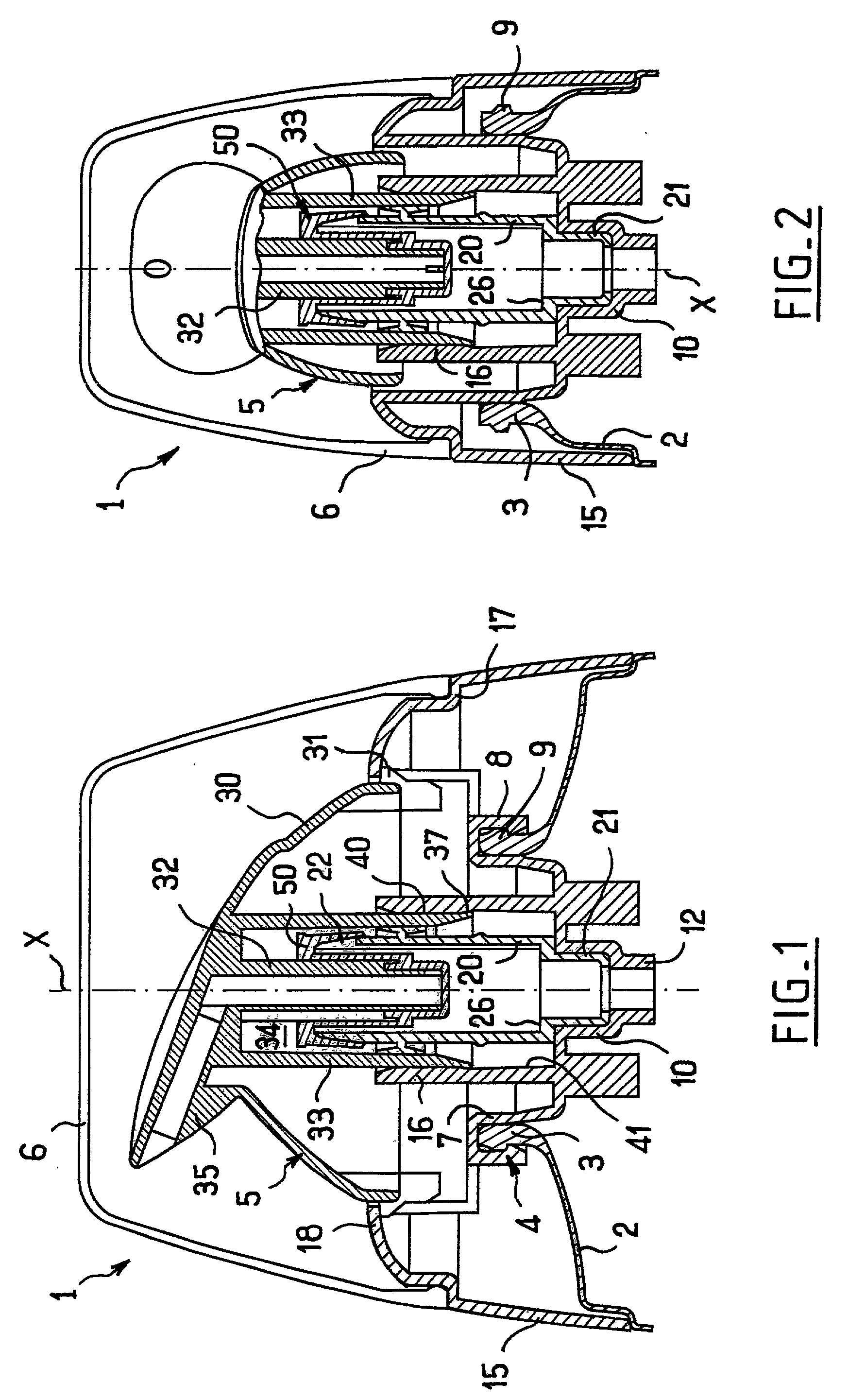
[0052] FIG. 1 shows a receptacle 1 having a tank-forming body 2, and the drawing shows only the top end thereof which defines a neck 3 onto which a support 4 is snap-fastened.

[0053] The support 4 constitutes a guide for mounting a pushbutton 5 to slide along an axis X, and it also serves to mount a removable closure cap 6 that covers the pushbutton 5 before first use thereof.

[0054] In the embodiment described, the support 4 has a sealing skirt 7 bearing in leakproof manner against the inside surface of the neck 3.

[0055] The sealing skirt 7 is extended radially firstly outwards by fixing tabs 8 that are snap-fastened on an annular rim 9 of the neck 3, and secondly inwards by a stepped wall 10 defining an endpiece 12 for connection to a dip tube (not shown).

[0056] An outer skirt 15 and a guide skirt 16 are made as a one-piece molding of plastics material together with the sealing skirt 7, the fixing tabs 8, and the stepped wall 10.

[0057] The outer skirt 15 extends around the neck 3 of...


PUM


Abstract

A pump of the type comprising a moving member mounted to move relative to a support, the moving member having a central duct in which the substance to be dispensed penetrates via at least one opening, the support co-operating with the moving member to define a variable-volume pump chamber around said central duct, the pump having a diaphragm held by retaining means on the support, the diaphragm having a central portion in which one end of said central duct is inserted, the diaphragm having a valve-forming portion arranged to isolate the pump chamber from said opening(s) of the central duct while the volume of the pump chamber is increasing and the substance is being sucked into the pump chamber, the diaphragm also bearing against the moving member in such a manner that movement of the moving member to dispense the substance causes the diaphragm to be stretched elastically. The pump has means suitable, during movement of the moving member for dispensing the substance, for minimizing the stretching of the valve-forming portion of said diaphragm.

Description

[0001] The present invention relates to a pump and to a receptacle containing a liquid, e.g. a cosmetic or care cream, and fitted with such a pump.[0002] French patent FR-B-2 728 809 discloses a pump having a pushbutton movably mounted on a support secured to the receptacle containing the substance to be dispensed, the pushbutton having a central duct provided with a radial opening at its bottom end, the support defining a variable-volume pump chamber around said central duct. A diaphragm made of elastomer material is mounted on the support. The diaphragm has a central portion in the form of a sleeve that is open at its top end and closed at its bottom end. The central duct of the pushbutton is inserted in the diaphragm via one end until it bears against the end wall of the central portion of the diaphragm.[0003] The above diaphragm acts as a spring for returning the pushbutton to its initial position after dispensing a quantity of substance.[0004] It also acts as a delivery valve.[...

Claims


Application Information

Patent Timeline
Patent Type & Authority Applications(United States)
IPC IPC(8): B05B11/00B65D47/34F04B9/14F04B43/02
CPCB05B11/007B05B11/3001B05B11/3004B05B11/3064B05B11/3076B05B11/1004B05B11/1001B05B11/1064B05B11/1076
Inventor BONNINGUE, PHILIPPEBAUDIN, GILLES
Owner LOREAL SA
Why Eureka
Try Eureka