Miniature electrical ball and tube socket with self-capturing multiple-contact-point coupling

a technology of electrical ball and tube sockets and contactors, which is applied in the direction of coupling device connections, sustainable manufacturing/processing, and contact members penetrating/cutting insulation/cable strands, etc., can solve the problems of connectors sliding over the surface, limited density of sockets with contactors so made, and limited miniaturization density of mechanically stamped and formed springs. , to achieve the effect of reducing mechanical stress, low self-inductance, and less magneti

Inactive Publication Date: 2008-10-28
CENTIPEDE SYST
View PDF18 Cites 48 Cited by
  • Summary
  • Abstract
  • Description
  • Claims
  • Application Information

AI Technical Summary

Benefits of technology

[0028]A further advantage of the present invention is provided by a tubular connector with shaped prongs on a first end that engage a first ball and helical prongs on a second and opposing end that engage a second ball, whereby the prongs of the first end resiliently pull the first ball toward the second ball. This advantage enables use of an array of such connectors to attach an electronic device to a substrate without need for a mechanical retaining component to apply force urging the device toward the substrate.
[0029]Anther advantage of the present invention is provided by a tubular connector with shaped prongs on a first end that engage a first ball and shaped prongs on a second end that engage a second ball such that the first ball is relatively free to move with respect to the second ball in a plane perpendicular to the axis of the tubular connector. This motion offers advantages in relieving mechanical stress due to thermal expansion mismatch, shock, vibration, and other mechanical motion.
[0030]Yet another advantage is provided by the present invention embodied in a connector that has a low self inductance. Thin laser-cut grooves through the tube allow less magnetic flux penetration into the interior of the tube than a connector made of a helical wire spring. The self inductance of the connector of the present invention may be further reduced by making the helical prongs short, as they extend a small distance from a solid girth around the tubular connector. These and other aspects of the present invention allow a high performance connector.
[0031]Depending upon the embodiment, one or more of these benefits may exist. These and other benefits have been described throughout the present specification and more particularly below.
[0032]Various additional objects, features, and advantages of the present invention can be more fully appreciated with reference to the detailed description and accompanying drawings that follow.

Problems solved by technology

Miniaturization and density of the mechanically stamped and formed springs are limited by present capabilities to a certain size.
Although advances continue to be made in the manufacturing art of stamping and forming springs, sockets with contactors so made are limited in density by the complexity of stamping and forming vary small miniaturized springs.
Because of small compliance in a vertical direction, a miniature stamped and formed spring may be unable to accommodate motion of a contactor support relative to a ball mated to it, thereby allowing vibration, mechanical shock load and forces, flexure, and the like to cause the connector to slide over the surface of the ball.
It is known in the industry that repeated microscopic motion of one contact relative to a mating contact causes fritting or a build up of small particle debris that can lead to contact failure.
As connector assemblies are miniaturized, the molding and assembly process are increasingly difficult and costly, thereby limiting the extension of connectors based on formed spring contacts to very high densities.
The clamping force needed by BGA sockets that make contact by applying force vertically is an increasing problem as the number of contact bumps increases into the thousands.
Further, at higher frequencies and clock speeds, the size and the self inductance of connectors are becoming an important limitation to system performance.
If the detents and balls are of non-matching or of non-uniform size, looseness, non-uniform gripping force and loss of gripping ability may result.

Method used


Image

  • Miniature electrical ball and tube socket with self-capturing multiple-contact-point coupling
  • Miniature electrical ball and tube socket with self-capturing multiple-contact-point coupling
  • Miniature electrical ball and tube socket with self-capturing multiple-contact-point coupling

Examples


Embodiment Construction

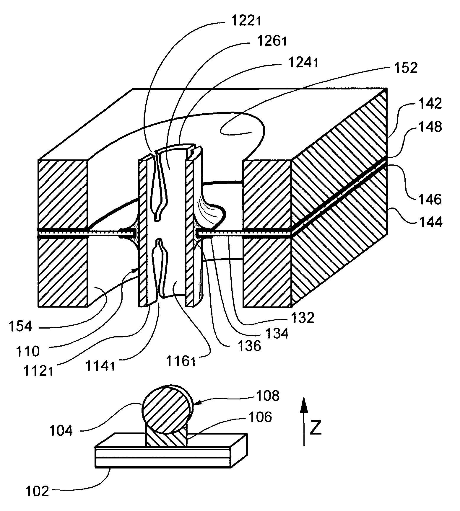
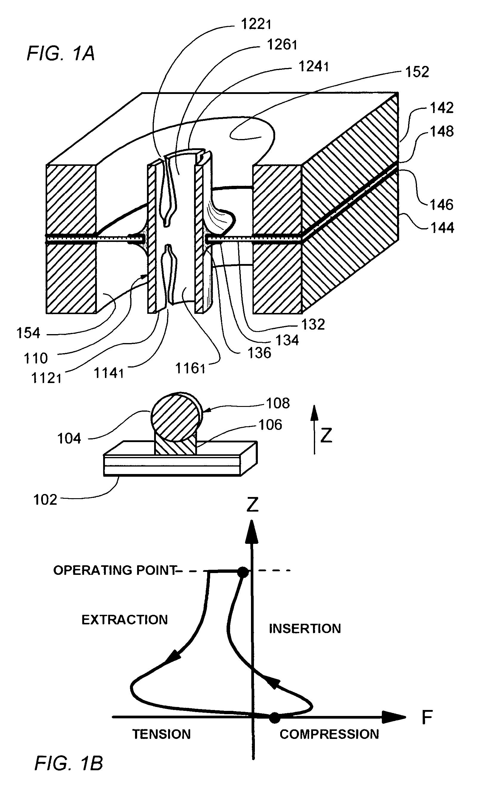
[0042]According to the invention, a high performance connector is provided for making reliable electrical connection to miniature and typically closely spaced terminals on an electronic device. More particularly, embodiments of the present invention provide a straight walled cylindrical metal tube that is cut in a pattern of slots of varying width into several prongs that are adapted to contact a bulbous terminal post around its circumference and to provide electrical contact thereto.

[0043]As illustrated in FIG. 1A, tubular connector 110 comprises a hollow cylindrical metal tube which is cut through on a bottom end by four slots 1141 to 1144 of variable width to form in this instance four prongs 1161 to 1164 terminated in four tips 1121 to 1124. For clarity of exposition, only one of each of the slots, prongs and tips is labeled in FIG. 1A. Prongs 1161 to 1164 are held in place by cylindrical collar region 120 in the un-sliced portion of the tube. The prongs are adapted to grip a bu...


PUM


Abstract

A socket connector for connecting a bulbous terminal or ball wherein the female element grips the terminal with resilient prongs with end tips at low insertion force but positive contact is maintained and wherein attempted withdrawal is normally inhibited by increasing force applied to the post by the female element in response to the withdrawal force. The female element comprises a tube of resilient conductive material that has been sliced or helically partitioned into opposing prongs of a width that decreases with axial distance from the end of the connector so as to allow the prongs of the connector to grip around the ball-like bulbous terminal and mechanically retain the terminal within the connector. The tubular element of the connector may be made by forming prongs in one or both ends of a tube by cuts of a width that increases with distance from the end of the tube.

Description

CROSS-REFERENCES TO RELATED APPLICATIONS[0001]This application relates to the subject matter similar to the subject matter found in commonly owned U.S. patent application Ser. No. 11 / 670,340 filed Feb. 2, 2007 and of commonly owned U.S. Provisional Patent Application Ser. No. 60 / 774,725 filed Feb. 17, 2006, the subject matter of which is incorporated herein by reference.BACKGROUND OF THE INVENTION[0002]This invention relates to miniature electrical connectors, as for example ball grid array (BGA) connectors, including connectors having pin dimensions of less than 1 millimeter in diameter and pin pitches of less than two millimeters. One or more embodiments of the present invention relate to a high performance electrical connector, that is a connector for supplying high current (relative to connectors of comparable size) and high frequency (RF) signals to high performance microelectronic devices, for example, and without limitation, integrated circuits (“ICs”), including microprocess...

Claims


Application Information

Patent Timeline
Patent Type & Authority Patents(United States)
IPC IPC(8): H01R12/00
CPCH01R4/027H01R12/58H05K3/3436H01R12/523H01R13/111H01R13/6315H05K2201/10242H05K2201/10424Y02P70/50
Inventor DI STEFANO, THOMAS H.
Owner CENTIPEDE SYST
Why Eureka
Try Eureka