Distance measuring apparatus having distance correction function

a technology of distance measurement and function, applied in the field of distance measuring equipment, can solve the problems of actual reference light producing timing delay, waveform blunting, and not fully solving problems, and achieve the effect of facilitating accurate distance correction

Active Publication Date: 2020-01-16
FANUC LTD
View PDF0 Cites 5 Cited by
  • Summary
  • Abstract
  • Description
  • Claims
  • Application Information

AI Technical Summary

Benefits of technology

[0009]Thus, there is a need for a distance measuring app

Problems solved by technology

Actual reference light produces timing delays and waveform blunting relative to ideal light emission timing of the reference light due to individual characteristics of the electronic elements of TOF cameras, in particular, semiconductor laser (LD), transistors, resistors, etc.
Though attempts ha

Method used


Image

  • Distance measuring apparatus having distance correction function
  • Distance measuring apparatus having distance correction function
  • Distance measuring apparatus having distance correction function

Examples


Embodiment Construction

[0017]The embodiments of the present disclosure will be described in detail below with reference to the attached drawings. In the drawings, identical or similar constituent elements have been assigned the same or similar reference numerals. Furthermore, the embodiments described below do not limit the technical scope of the inventions described in the claims or the definitions of terms.

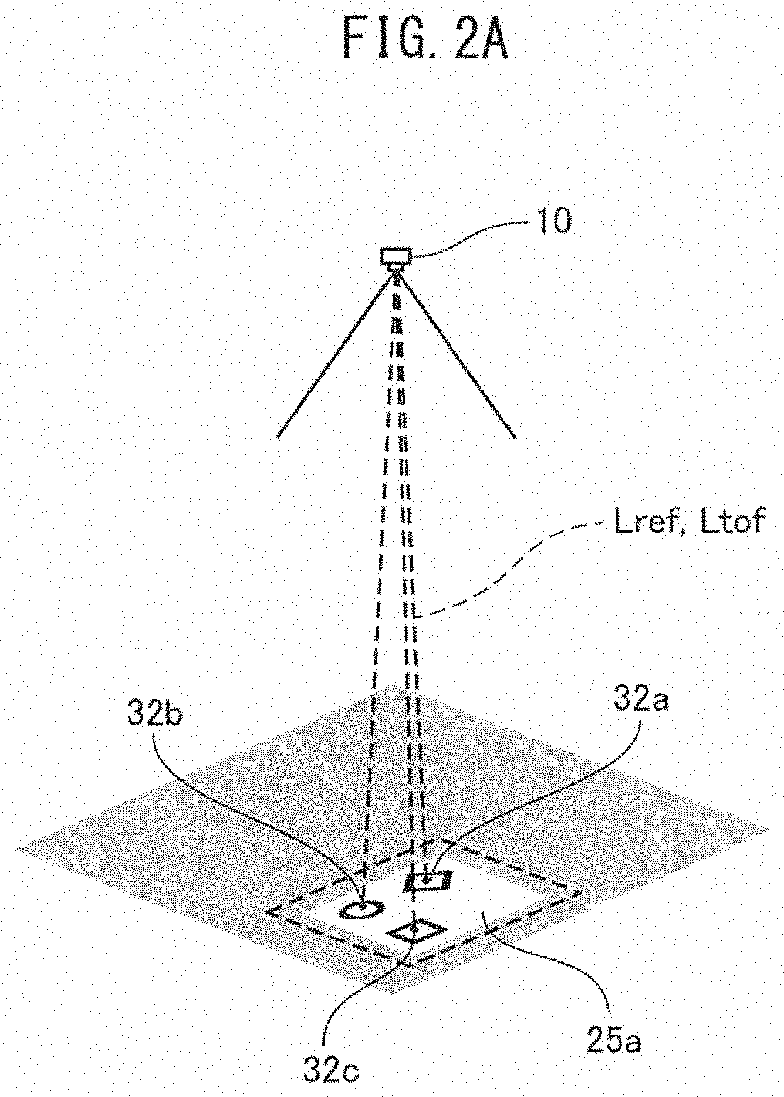
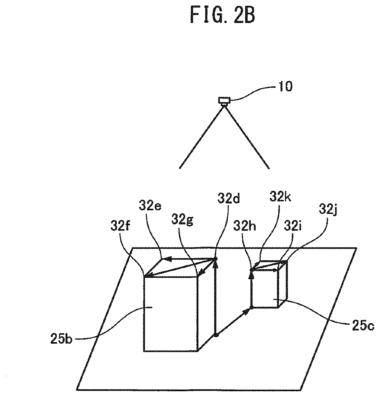
[0018]FIG. 1 is a block diagram of a distance measuring apparatus 10 according to the present embodiment. The distance measuring apparatus 10 is a TOF camera which measures a distance to an object based on, for example, a phase difference method. The distance measuring apparatus 10 comprises a light emitting section 11 which emits reference light L1 emitted to a target measurement space, a light receiving section 12 which receives incident light L2 from the target measurement space, and a distance image generation section 13 which generates a distance image to the object in the target measurement spac...


PUM


Abstract

A distance measuring apparatus includes a reference object distance calculation section which calculates a distance to a reference object based on a two-dimensional image in which the reference object, which includes a plurality of feature points having obvious three-dimensional coordinate correlations, is captured, and a correction amount calculation section which calculates a correction amount for correcting a distance image by comparing the calculated distance to the reference object with a distance measurement value to the reference object in the distance image.

Description

BACKGROUND OF THE INVENTION1. Field of the Invention[0001]The present invention relates to a distance measuring apparatus which measures a distance to an object based on a time of flight of light, and in particular, relates to a distance measuring apparatus having a distance correction function.2. Description of the Related Art[0002]TOF (time of flight) cameras which output a distance based on the time of flight of light are known as a distance measuring apparatus for measuring the distance to the object. Many TOF cameras use a phase difference method in which measurement light with an intensity modulated over predetermined cycles is irradiated a target measurement space, and a phase difference between the irradiated measurement light and the light reflected by the object in the target measurement space is detected.[0003]TOF cameras, which are three-dimensional sensors, cause distance measurement errors due to individual characteristic variations in electronic elements thereof (e.g....

Claims


Application Information

Patent Timeline
IPC IPC(8): G01S7/497G01S17/08G01S17/89G01S7/491
CPCG01S7/497G01S7/4915G01S17/89G01S17/08G01S17/48G01S17/894
Inventor NAKAMURA, MINORUTAKAHASHI, YUUKIWATANABE, ATSUSHI
Owner FANUC LTD
Why Eureka
Try Eureka