Reciprocal channel sounding reference signal multiplexing

a reference signal and channel sounding technology, applied in the direction of digital transmission, electrical equipment, transmission path sub-channel allocation, etc., can solve the problems of not being able to achieve reciprocity for cellular networks, no single signal that is able to achieve all above functionality, and other types of signals that do not scale well

Active Publication Date: 2016-09-15
QUALCOMM INC
View PDF3 Cites 40 Cited by
  • Summary
  • Abstract
  • Description
  • Claims
  • Application Information

AI Technical Summary

Problems solved by technology

There is no single signal that is able to achieve all of above functionality for UEs.
Reciprocity has not been available for cellular networks because current approaches require reference signals specific for particular antennas, such as CSI-RS in the long term evolution (LTE) context.
Further, CSI-RS and other types of signals do not scale well, which is becoming an ever-increasing issue as the demand for mobile broadband continues to increase.

Method used


Image

  • Reciprocal channel sounding reference signal multiplexing
  • Reciprocal channel sounding reference signal multiplexing
  • Reciprocal channel sounding reference signal multiplexing

Examples


Embodiment Construction

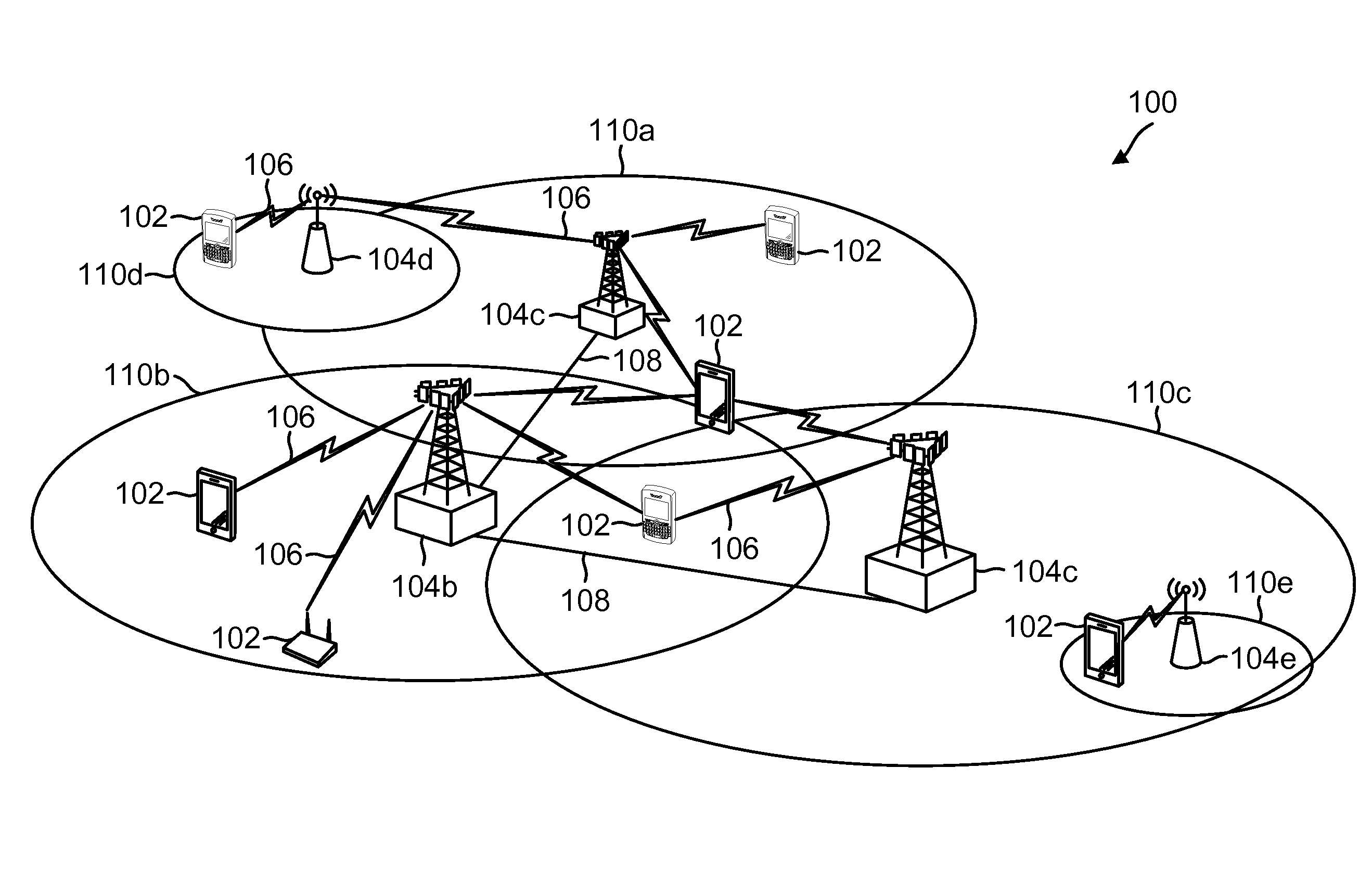
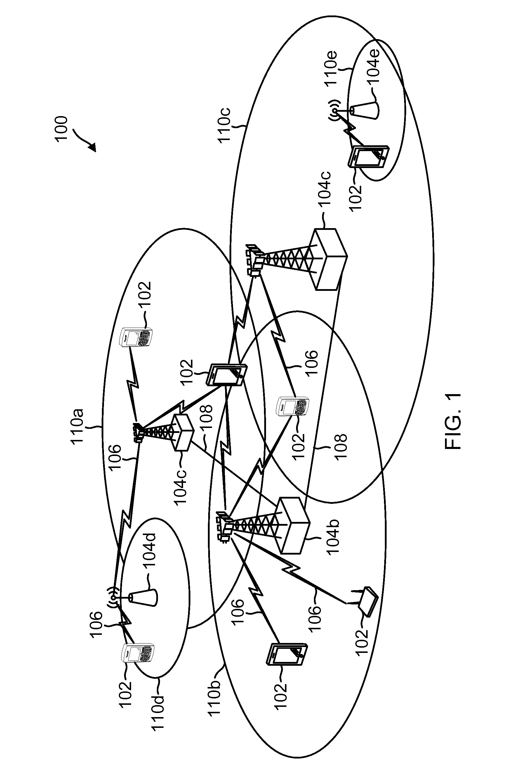
[0033]The detailed description set forth below, in connection with the appended drawings, is intended as a description of various configurations and is not intended to represent the only configurations in which the concepts described herein may be practiced. The detailed description includes specific details for the purpose of providing a thorough understanding of the various concepts. However, it will be apparent to those skilled in the art that these concepts may be practiced without these specific details. In some instances, well-known structures and components are shown in block diagram form in order to avoid obscuring such concepts.

[0034]The techniques described herein may be used for various wireless communication networks such as CDMA, TDMA, FDMA, OFDMA, SC-FDMA and other networks. The terms “network” and “system” are often used interchangeably. A CDMA network may implement a radio technology such as Universal Terrestrial Radio Access (UTRA), cdma2000, etc. UTRA includes Wide...


PUM


Abstract

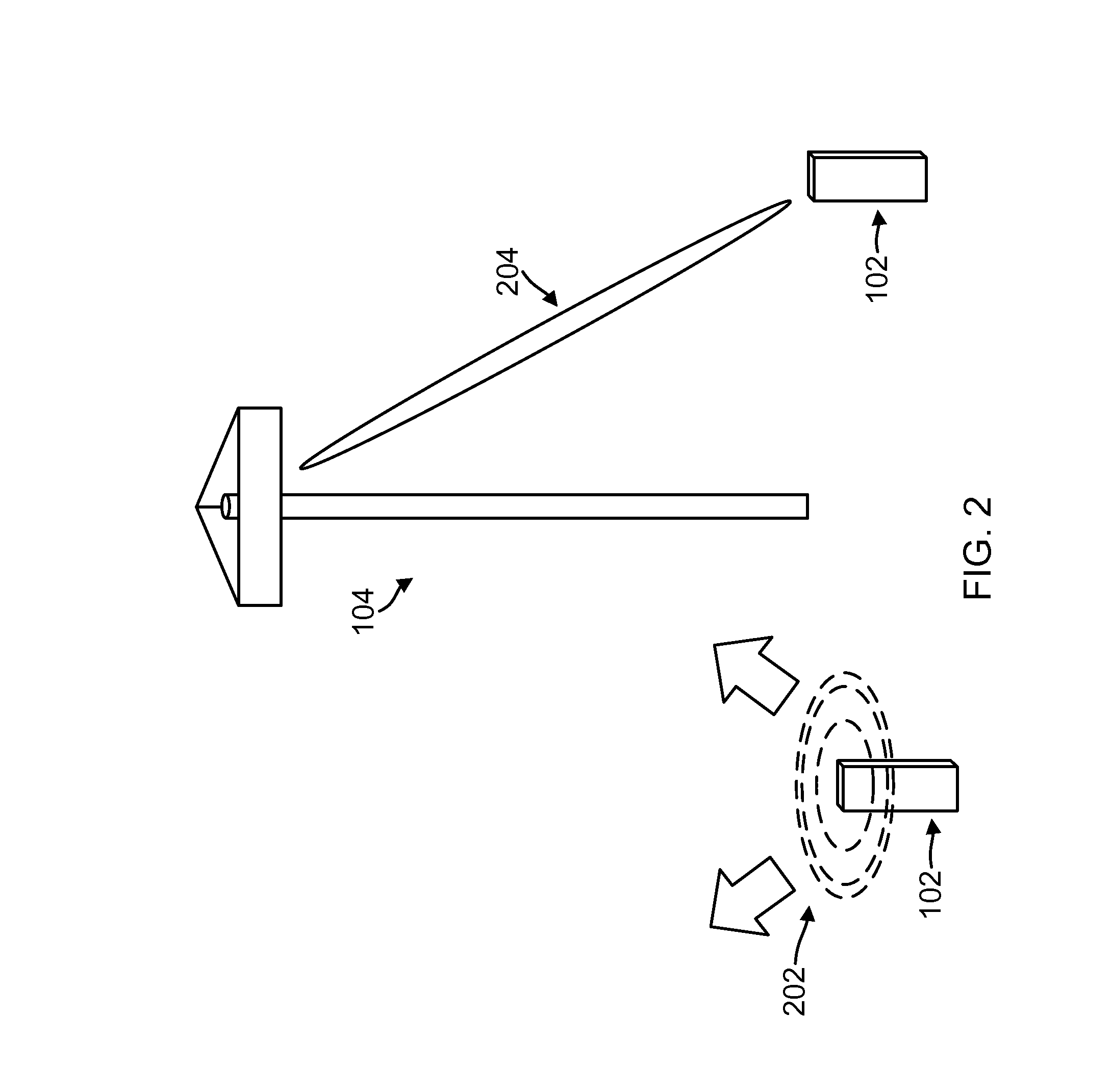
Systems and techniques are disclosed to enhance the efficiency of available bandwidth between UEs and base stations. A UE transmits a sounding reference signal (SRS) to the base station. The base station characterizes the uplink channel based on the SRS received and, using reciprocity, applies the channel characterization for the downlink channel. As part of applying the channel information, the base station forms the beam to the UE based on the uplink channel information obtained from the SRS. The UE may include an array of antennas, each UE transmitting a different SRS that the base station receives and uses to characterize the downlink. Multiple UEs (or a single UE with multiple antennas) transmit SRS at the same time and frequency allocation (non-orthogonal), but with each sending its own unique SRS. Further, multiple UEs (or a single UE with multiple antennas) may send their SRS at unique time / frequency allocations (orthogonal).

Description

CROSS REFERENCE TO RELATED APPLICATIONS & PRIORITY CLAIM[0001]The present application claims priority to and the benefit of the U.S. Provisional Patent Application No. 62 / 133,334, filed Mar. 14, 2015, which is hereby incorporated by reference in its entirety.TECHNICAL FIELD[0002]This application relates to wireless communication systems, and more particularly to using channel state information obtained from an uplink sounding signal in non-orthogonal or orthogonal applications to beamform downlink messages to targeted recipients.INTRODUCTION[0003]A wireless communication network may include a number of base stations that can support communication for a number of user equipments (UEs). In recent years, the carrier frequencies at which base stations and UEs communicate have continued to increase and include larger bandwidths. To take advantage of these higher frequencies, more antennas in the same physical space have been used. For these higher frequency bands to be useful and approxi...

Claims


Application Information

Patent Timeline
Patent Type & Authority Applications(United States)
IPC IPC(8): H04L5/00
CPCH04L5/0048H04B7/0452H04L5/0051H04B7/0617
Inventor SORIAGA, JOSEPH BINAMIRAJIANG, JINGMUKKAVILLI, KRISHNA KIRANVITTHALADEVUNI, PAVAN KUMARBHUSHAN, NAGAJI, TINGFANGSMEE, JOHN EDWARD
Owner QUALCOMM INC
Why Eureka
Try Eureka