Liquid supplying apparatus and endoscope reprocessing apparatus

Active Publication Date: 2016-09-22
OLYMPUS CORP
View PDF1 Cites 5 Cited by
  • Summary
  • Abstract
  • Description
  • Claims
  • Application Information

AI Technical Summary

Benefits of technology

[0008]A liquid supply apparatus according to one aspect of the present invention includes: a storing tank configured to store a liquid; a supply conduit through which the liquid remained inside the supply conduit flows reversely into the storing tank by a predetermined amount over time, the supply conduit having a first end portion connected to the storing tank; a liquid feeding section which is arranged at the storing tank or the supply conduit, an

Problems solved by technology

Presence of air in the supply conduit causes unevenness in the v

Method used


Image

  • Liquid supplying apparatus and endoscope reprocessing apparatus
  • Liquid supplying apparatus and endoscope reprocessing apparatus
  • Liquid supplying apparatus and endoscope reprocessing apparatus

Examples


first embodiment

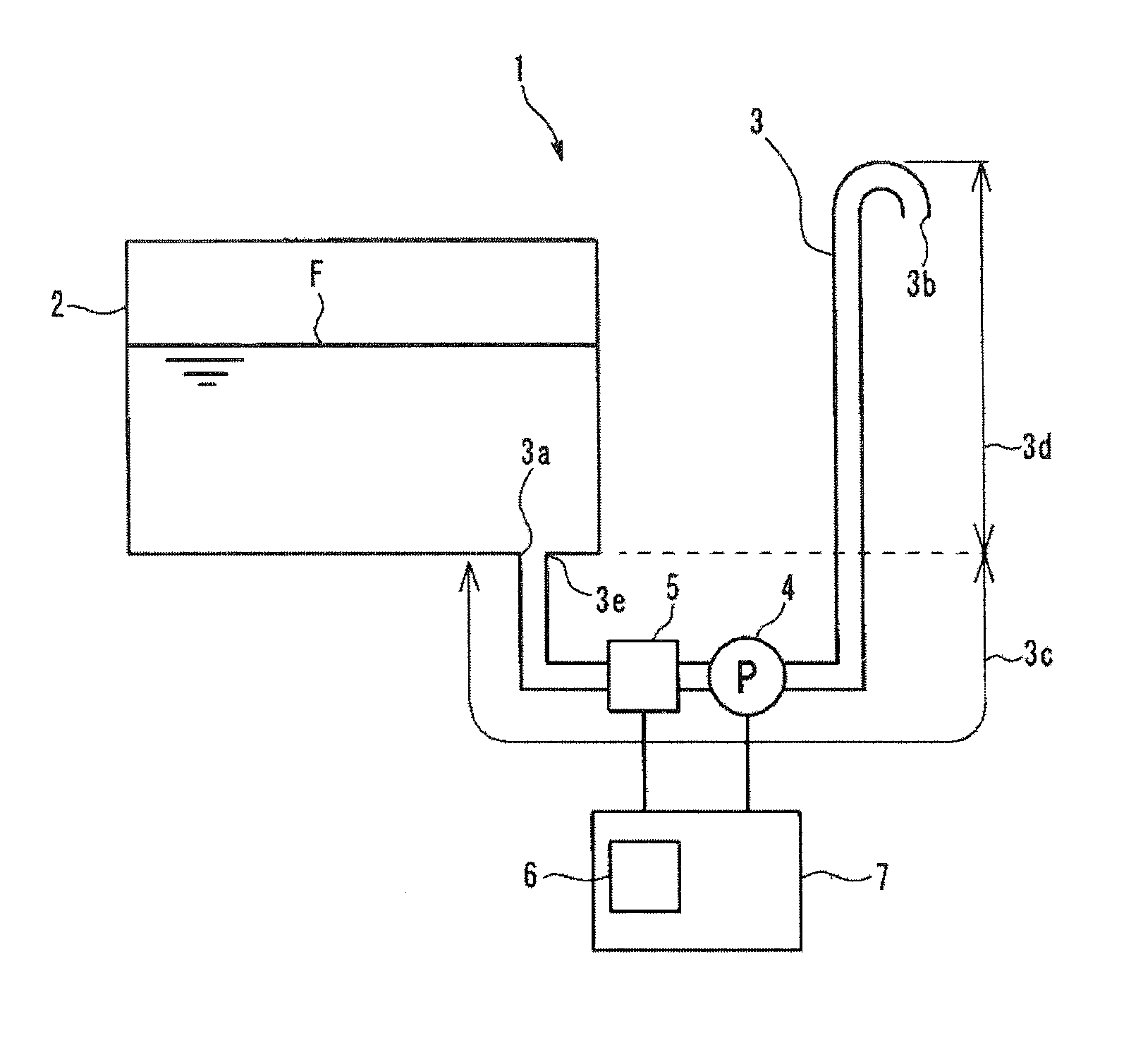
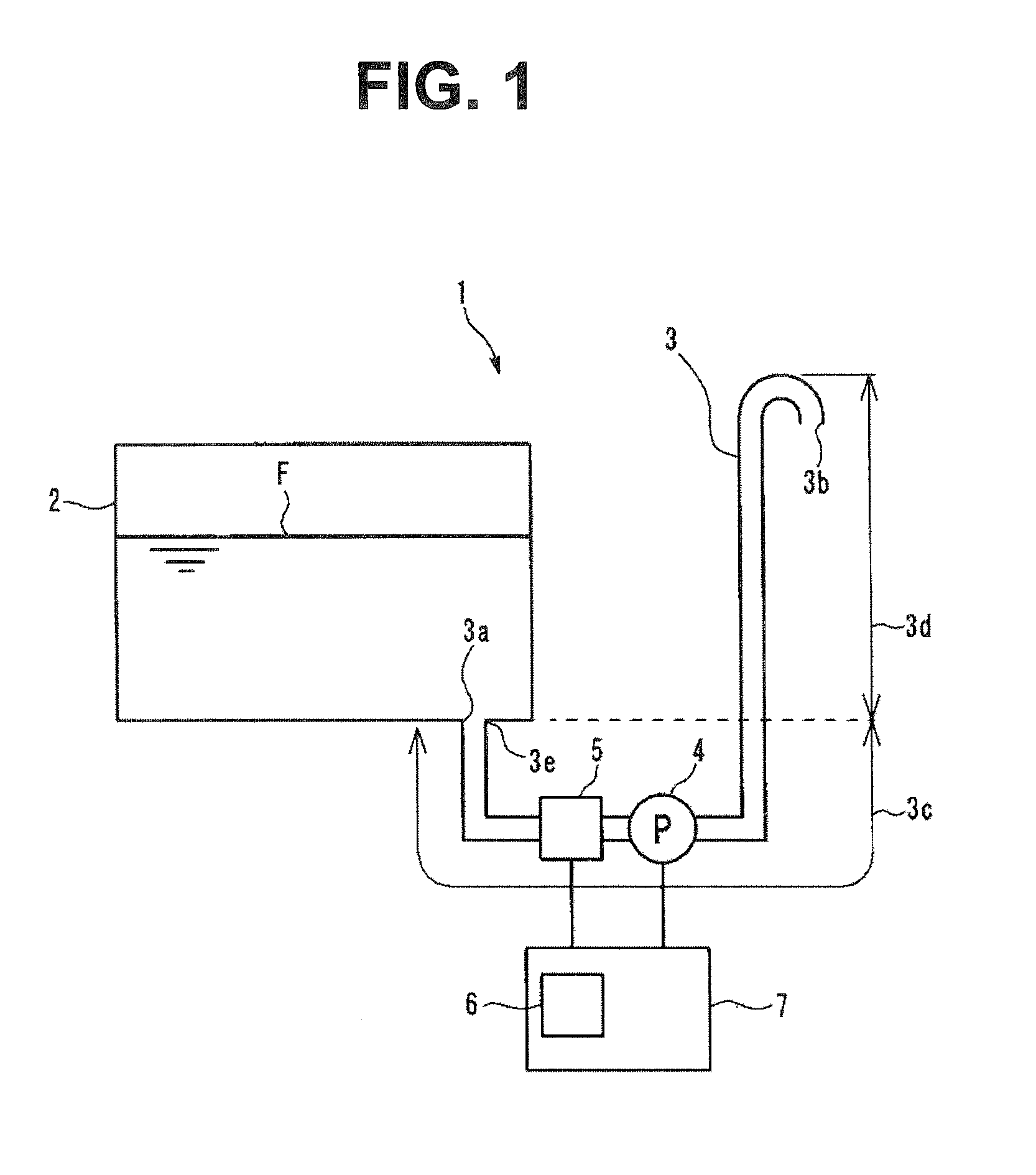
[0023]Hereinafter, description will be made on the first embodiment as one example of the embodiments of the present invention. A liquid supply apparatus 1 according to the present embodiment as shown in FIG. 1 includes a storing tank 2 that stores a liquid F, a supply conduit 3 including a first end portion 3a connected to the storing tank 2, and a liquid feeding section 4 that feeds the liquid F in the storing tank 2 to a second end portion 3b of the supply conduit 3 through the supply conduit 3. In addition, the liquid supply apparatus 1 includes a liquid flow detection section 5, a time measuring section 6, and a control section 7.

[0024]Schematically, the liquid supply apparatus 1 is an apparatus that operates the liquid feeding section 4, to thereby discharge the liquid F in the storing tank 2 from the second end portion 3b of the supply conduit 3. The liquid supply apparatus 1 is incorporated in an apparatus that uses the liquid F. As described later, in the present embodiment...

second embodiment

[0079]Next, description will be made on the second embodiment of the present invention. Hereinafter, only the points different from the first embodiment will be described. The same constituent elements as those in the first embodiment are attached with the same reference numerals and description thereof will be appropriately omitted.

[0080]In the above-described first embodiment, the liquid flow detection section 5 is arranged at the first conduit 3c. In the present embodiment, the liquid flow detection section 5 is arranged at the second conduit 3d, as shown in FIG. 8.

[0081]When the liquid flow detection section 5 is arranged at the second conduit 3d as in the present embodiment, there is a case where the liquid level of the liquid F in the supply conduit 3 falls below the liquid flow detection section 5 depending on the elapsed time Ts after the stop of the liquid feeding in the main liquid feeding process. Therefore, in the preliminary liquid feeding process in the liquid supply a...

third embodiment

[0086]Next, the third embodiment of the present invention will be described. Hereinafter, only the points different from the first and second embodiments will be described below. The same constituent elements as those in the first and second embodiments are attached with the same reference numerals and descriptions thereof will be appropriately omitted.

[0087]In the liquid supply apparatus 1 in the above-described first embodiment, the supply conduit 3 includes the first conduit 3c which is the section disposed at the position lower than the storing tank 2. On the other hand, in the liquid supply apparatus 1 according to the present embodiment shown in FIG. 10, the supply conduit 3 is arranged so as not to pass below the storing tank 2.

[0088]Specifically, the supply conduit 3 according to the present embodiment is arranged such that the entirety of the supply conduit 3 is located at the position upper than the bottom face of the storing tank 2. The first end portion 3a of the supply ...


PUM


Abstract

A liquid supply apparatus includes: a storing tank configured to store a liquid; a supply conduit through which the liquid remained inside the supply conduit flows reversely into the storing tank by a predetermined amount over time, the supply conduit having a first end portion connected to the storing tank; a liquid feeding section which is arranged at the storing tank or the supply conduit, and which is configured to feed the liquid from the storing tank to a second end portion of the supply conduit; a time measuring section which measures an elapsed time from stop of the liquid feeding by the liquid feeding section; and a control section which is connected to the liquid feeding section and the time measuring section and which is configured to drive the liquid feeding section for a predetermined time based on a length of the elapsed time.

Description

CROSS REFERENCE TO RELATED APPLICATION[0001]This application is a continuation application of PCT / JP2015 / 058327 filed on Mar. 19, 2015 and claims benefit of Japanese Application No. 2014-146203 filed in Japan on Jul. 16, 2014, the entire contents of which are incorporated herein by this reference.BACKGROUND OF THE INVENTION[0002]1. Field of the Invention[0003]The present invention relates to a liquid supply apparatus and an endoscope reprocessing apparatus that include a liquid supply conduit for discharging a liquid in a storing tank.[0004]2. Description of the Related Art[0005]Endoscopes for use in medical fields are subjected to processing using fluid such as cleaning processing and disinfecting processing after being used. As an apparatus that automatically performs cleaning processing and disinfecting processing on an endoscope, for example, the endoscope reprocessing apparatus as disclosed in Japanese Patent Application Laid-Open Publication No. 2010-57752 is known.[0006]The e...

Claims


Application Information

Patent Timeline
IPC IPC(8): A61B1/12A61L2/18B67D7/62B67D7/76B08B3/08G05D7/06
CPCA61B1/123B08B3/08G05D7/0676A61L2202/24B67D7/763A61L2/18B67D7/62A61B1/12B01J4/00B08B3/04
Inventor YASHIMA, TAIKIKOMIYA, TAKAAKI
Owner OLYMPUS CORP
Why Eureka
Try Eureka