Cover for an electronic module

Active Publication Date: 2016-09-22
TE CONNECTIVITY CORP
View PDF8 Cites 1 Cited by
  • Summary
  • Abstract
  • Description
  • Claims
  • Application Information

AI Technical Summary

Benefits of technology

The patent text describes a cover for an electronic module that provides electrical shielding for the module. The cover has a connector portion that is integrated with a cover plate, and includes a plurality of contact channels for receiving a plug connector. The contacts have mating ends that can connect to the plug connector, and mounting ends that can be soldered to the circuit board. The technical effect of this invention is to provide better protection and reliability for electronic modules, especially in high-density connectivity applications.

Problems solved by technology

However, alignment of the header connector with the opening in the cover is problematic and misalignment may lead to contact stubbing.
The two-piece design requires time for assembly and requires the parts to be manufactured to tight tolerances, which increases the overall cost of the product.
Additionally, problems arise over time of the header assembly vibrating out of the shroud after continued use, which leads to failure of the lamp assembly.

Method used


Image

  • Cover for an electronic module
  • Cover for an electronic module
  • Cover for an electronic module

Examples


Embodiment Construction

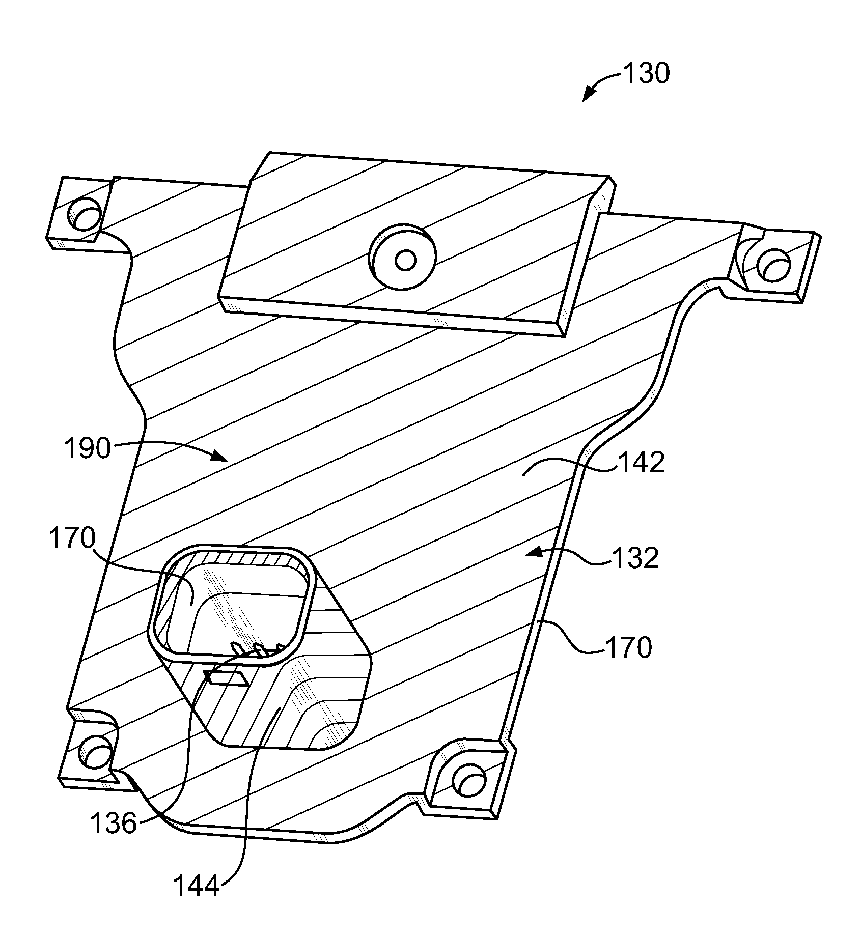
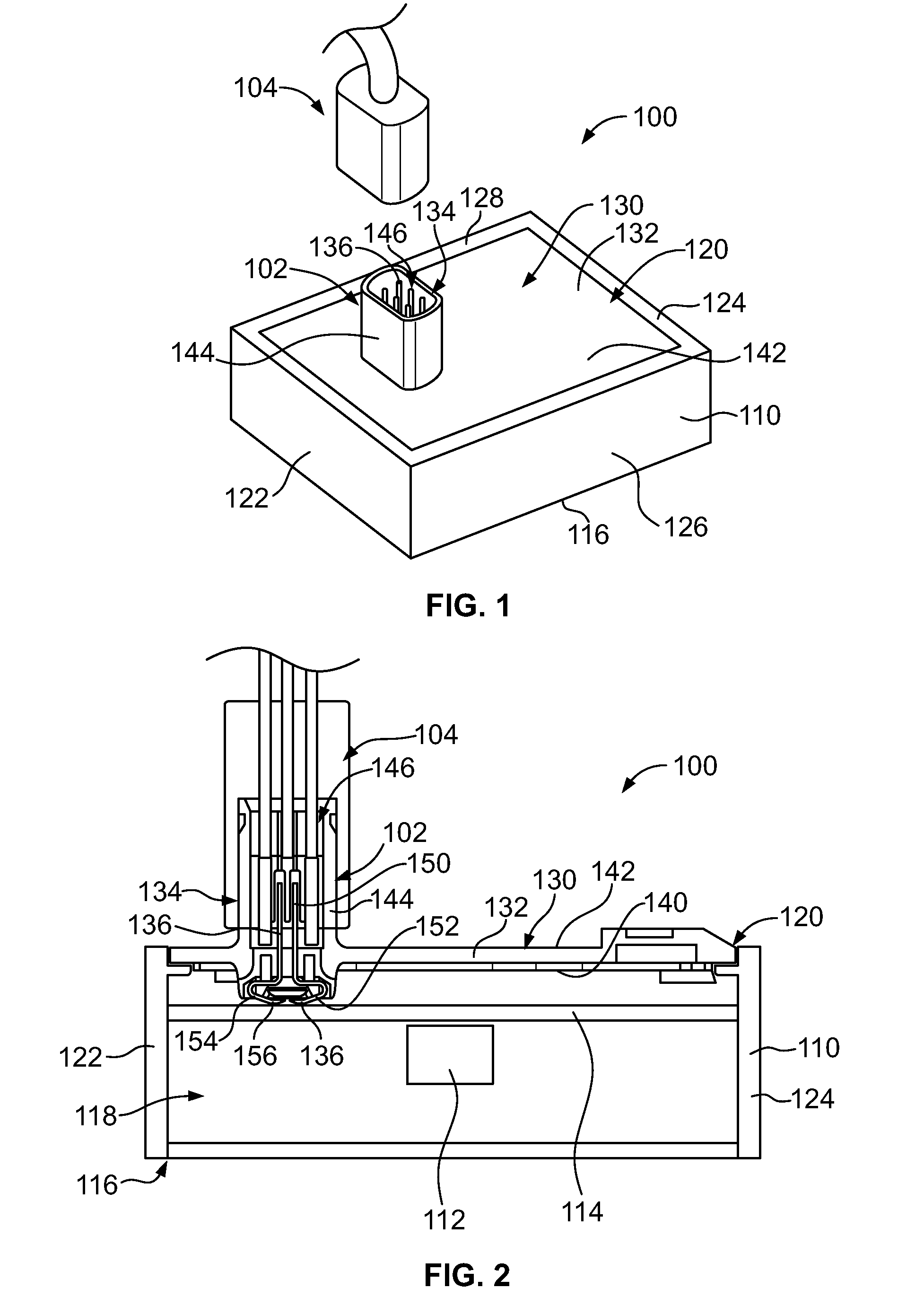
[0011]FIG. 1 is a perspective view of an electronic module 100 formed in accordance with an exemplary embodiment. FIG. 2 is a cross-sectional view of the electronic module 100. The electronic module 100 has an electrical connector 102 configured to be electrically connected to a plug connector 104. Optionally, the plug connector 104 may be a power connector configured to supply power to the electronic module 100; however the plug connector 104 may additionally or alternatively transmit data signals.

[0012]In an exemplary embodiment, the electronic module 100 is a lamp assembly and may be referred to hereinafter as a lamp assembly 100. While various features are described herein with reference to a lamp assembly, the subject matter described herein is applicable to other types of electronic modules 100 and is not intended to be limited to a lamp assembly. In an exemplary embodiment, the electronic module 100 may be used in an automotive application; however, the subject matter describ...


PUM


Abstract

A cover for an electronic module that has a housing holding a electrical component and a circuit board for operating the electrical component includes a cover plate having an interior surface and an exterior surface. The cover plate has a dielectric body. A majority of at least one of the interior surface and the exterior surface includes a conductive layer to provide electrical shielding for the cover plate. A connector portion is formed integrally with the cover plate defining a unitary structure. The connector portion includes a plurality of contact channels and a shroud extending from the exterior surface that surrounds a receptacle configured to receive a plug connector therein. Contacts are held in corresponding contact channels that have mating ends positioned in the receptacle and mounting ends exposed beyond the interior surface for mounting to the circuit board.

Description

BACKGROUND OF THE INVENTION[0001]The subject matter herein relates generally to covers for electronic modules.[0002]Electronic modules, such as lamp assemblies, typically have a housing or enclosure that houses electrical components, such as a lighting element, a circuit board for controlling operation of the electrical components and wires or electrical connectors that supply power to the electrical components. Conventional lamp assemblies typically include a header connector that is mounted to the circuit board. A cover includes an opening therethrough and a shroud configured to receive a plug connector. In at least some known lamp assemblies, the housing is manufactured from a metal material to provide electrical shielding. The header connector is aligned with and passes into the shroud for electrical connection to the plug connector. However, alignment of the header connector with the opening in the cover is problematic and misalignment may lead to contact stubbing. Furthermore,...

Claims


Application Information

Patent Timeline
IPC IPC(8): H05K5/03H05K7/02H01R13/6581
CPCH05K5/03H05K7/02H01R13/6581H01R12/714H01R13/502H01R13/5213H01R13/658H01R13/6658
Inventor GINGRICH, III, CHARLES RAYMOND
Owner TE CONNECTIVITY CORP
Why Eureka
Try Eureka