Percutaneous Disc Clearing Device

a disc clearing and percutaneous technology, applied in the field of percutaneous disc clearing devices, can solve the problems of unable to reach the locations of the affected area, relative stiffness of the instrument, and limited flexibility of the working channel

Active Publication Date: 2016-10-06
MEDOS INT SARL
View PDF3 Cites 51 Cited by
  • Summary
  • Abstract
  • Description
  • Claims
  • Application Information

AI Technical Summary

Benefits of technology

[0020]The disc removal tool can be actively steered, so that it can sweep within the disc, and detach disc material at locations where a stiff instrument (if introduced through the same working channel) could never reach. The disc removal member has the necessary steering stability and bending radius to reach and clear a sufficient amount of disc area, while being introduced and operated through a rigid and straight working channel.

Problems solved by technology

In contrast, a relatively stiff instrument—if introduced through the same limited-flexibility working channel—could never reach those locations.

Method used


Image

  • Percutaneous Disc Clearing Device
  • Percutaneous Disc Clearing Device
  • Percutaneous Disc Clearing Device

Examples


Embodiment Construction

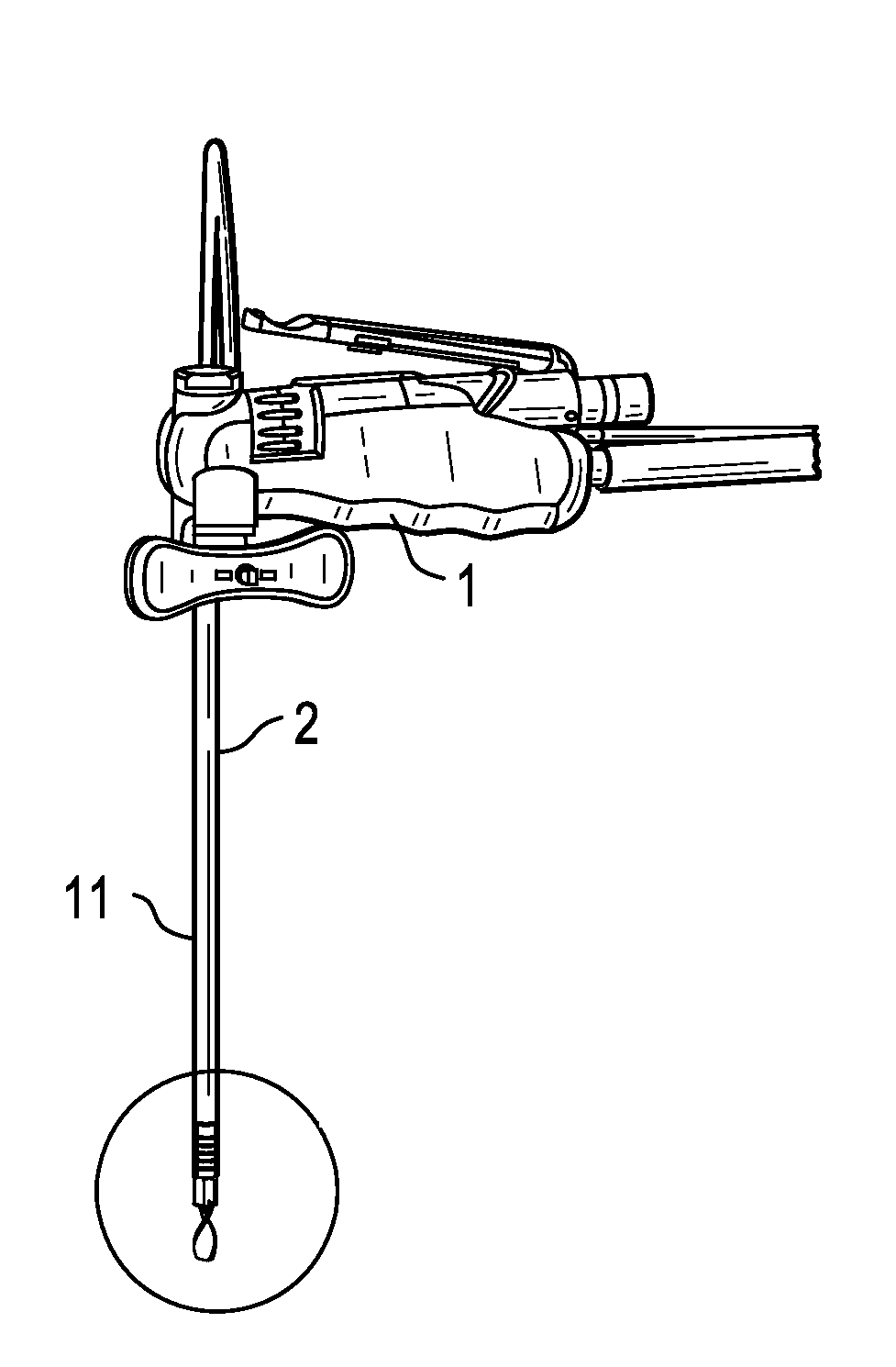
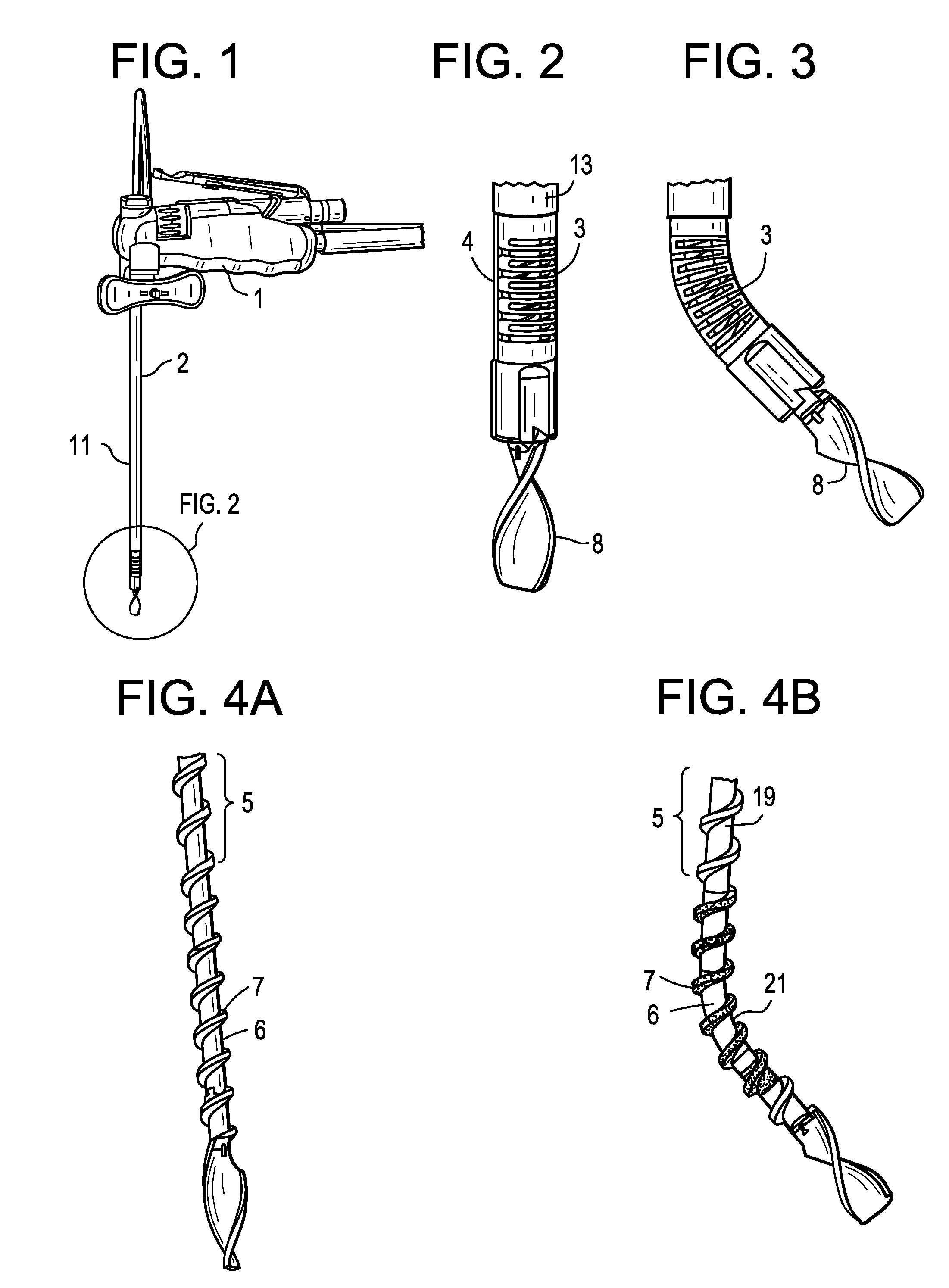
[0069]Referring now to FIGS. 1-4B, there is provided a discectomy tool comprising:[0070]a) a cannula 11 having an outer surface 13 having a longitudinal bore therein, a rigid proximal end portion 2 and a flexible distal end portion 3;[0071]b) a steering wire 4 longitudinally contacting the cannula and extending in the direction of the longitudinal bore;[0072]c) a flexible, hollow transmission shaft 5 disposed in the cannula, the shaft having a throughbore, a proximal end portion 19, a flexible 6 distal end portion and an outer surface 21 having a flexible thread 7 extending therefrom;[0073]d) an irrigation source fluidly connected to the throughbore;[0074]e) a cutting tip 8 attached to the distal end portion of the transmission shaft; and[0075]f) a drive / steer / irrigation handle 1.

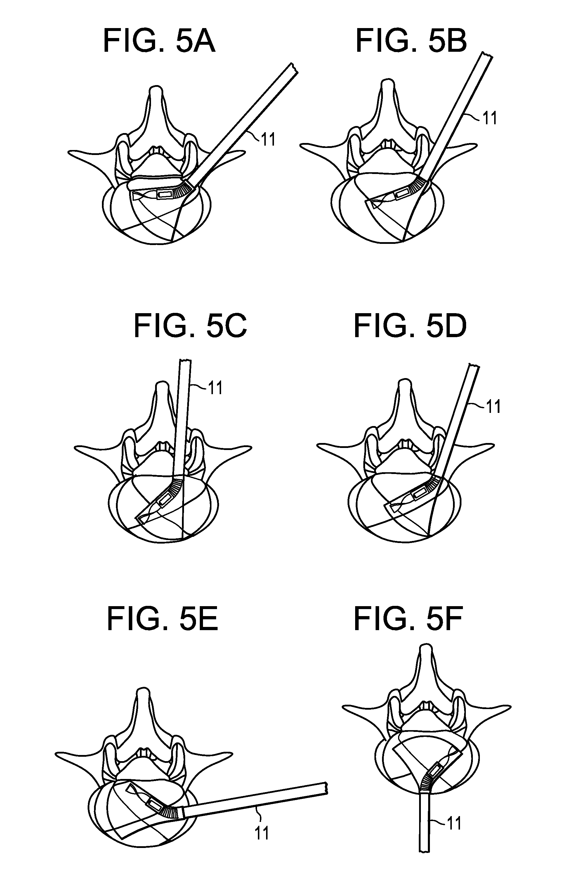
[0076]The invention is not limited to any particular approach trajectory of the working channel. For example, if a certain approach / trajectory offers an advantage in a given situation, the approach can be c...


PUM


Abstract

A discectomy tool comprising:
  • a) a cannula having an outer surface having a longitudinal bore therein, a proximal end and a distal end;
  • b) a steering wire disposed in the longitudinal bore;
  • c) a flexible, hollow transmission shaft disposed in the cannula, the shaft having a throughbore, a proximal end portion, a distal end portion and an outer surface having a thread extending therefrom;
  • d) an irrigation source fluidly connected to the throughbore;
  • e) a cutting tip attached to the distal end portion of the transmission shaft.

Description

BACKGROUND OF THE INVENTION[0001]Lumbar interbody fusion is a surgical procedure that is often performed up on instabilities within the lumbar spine. These instabilities are either the result of a medical condition like degenerative disc disease (DDD) or a vertebral bone fracture, or the result of a surgical decompression procedure treating stenosis, in which soft tissue and / or bony structures around compressed neural structures in the spine are removed. To achieve an acceptable interbody fusion, the existing disc needs to be removed (discectomy), and bone graft and / or an implanted cage is put on its place.[0002]There are several approaches through which the disc clearing and cage insertion steps can be performed, each with its benefits and risks. One of the most popular is the transforaminal approach, commonly used in a transforaminal lumbar interbody fusion (TLIF).[0003]In a TLIF approach, the creation of an access window that is necessary to insert the cage (implant) normally req...

Claims


Application Information

Patent Timeline
Patent Type & Authority Applications(United States)
IPC IPC(8): A61B17/16
CPCA61B17/1617A61B17/1642A61B2217/007A61B2017/00323A61B17/1671A61B17/1631A61B17/1633A61B17/1644A61B17/32002A61B2017/320032A61B2017/00261A61B2217/005A61B2017/00685A61B2017/00309
Inventor CHEGINI, SALMANRICHTER, JOERNTHOMMEN, DANIEL
Owner MEDOS INT SARL
Why Eureka
Try Eureka