Supercharge Your Innovation With Domain-Expert AI Agents!

Dynamic tracing framework for debugging in virtualized environments

a virtualized environment and dynamic tracing technology, applied in the field of debugging, can solve the problems of complex identification and correlation of the sequence of events within the collected debug data, and achieve the effect of reducing the complexity of the correlation

Inactive Publication Date: 2016-10-06
INT BUSINESS MASCH CORP
View PDF5 Cites 1 Cited by
  • Summary
  • Abstract
  • Description
  • Claims
  • Application Information

AI Technical Summary

Problems solved by technology

All of the debug data is collected at the same time across all of the software systems, and the identification and correlation of the sequence of events within the collected debug data may be very complex.

Method used


Image

  • Dynamic tracing framework for debugging in virtualized environments
  • Dynamic tracing framework for debugging in virtualized environments
  • Dynamic tracing framework for debugging in virtualized environments

Examples


Embodiment Construction

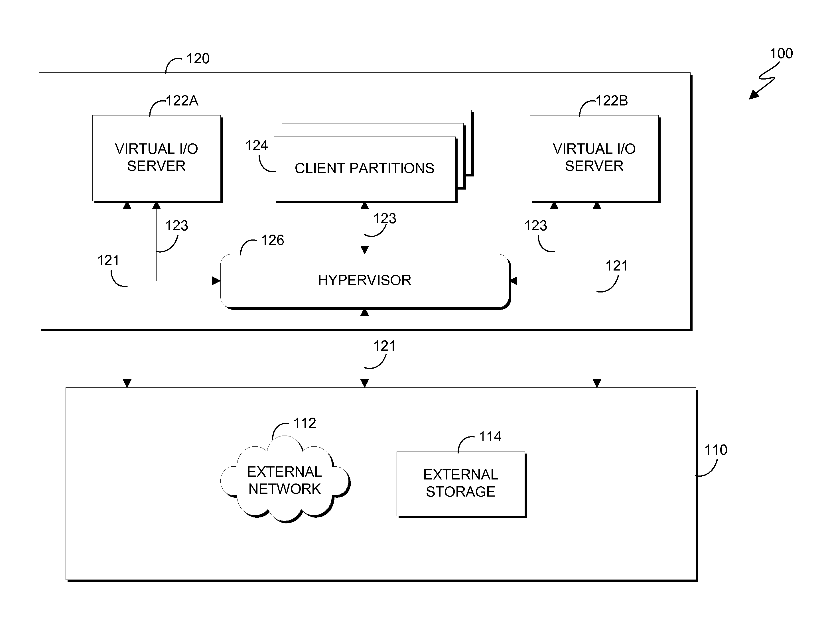
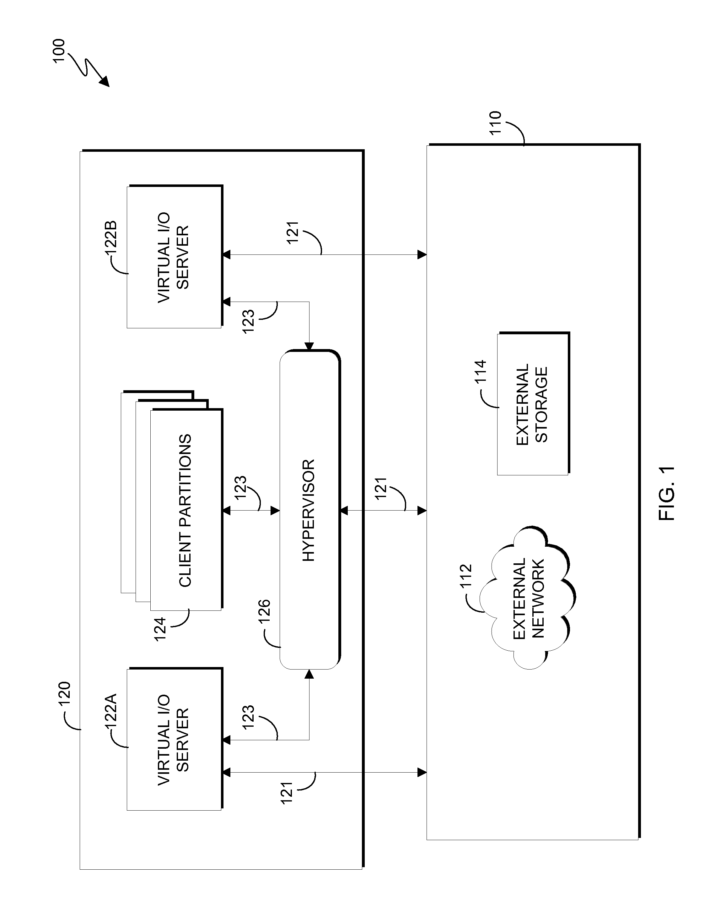
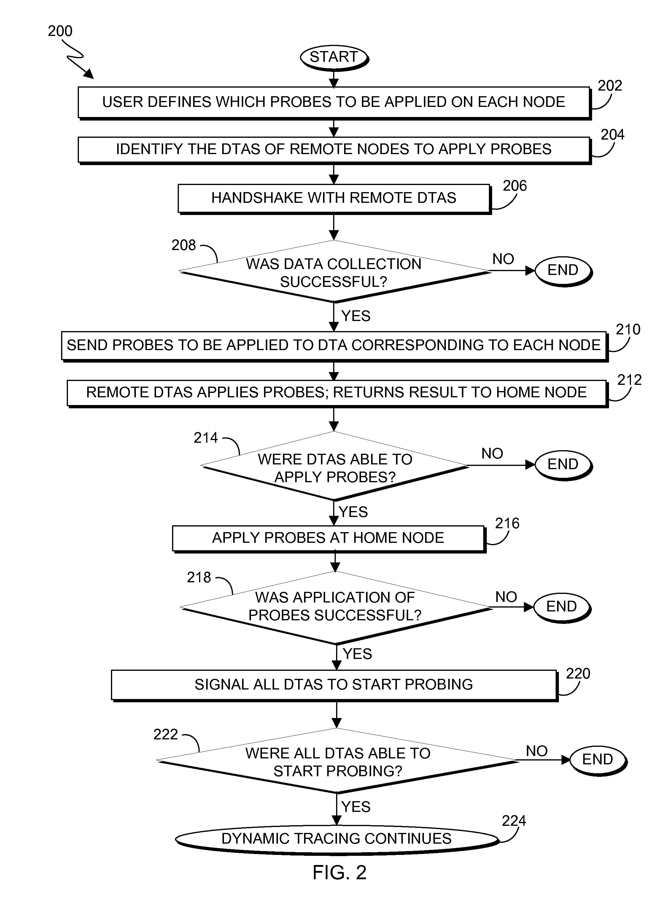
[0010]Debugging issues or failures in virtualized environments may often be very complex. Known tools exist to capture debug data independently in each of the software systems and are later post processed in identifying the specific component, which can be tedious and time consuming. Also, the existing debug tools produce large quantities of debug data, which can take hours to days for an expert to analyze. In order to overcome issues associated with the debugging process, a dynamic tracing approach has been introduced in which a user may implant debug points and collect varied data, as required, on the fly, without having to recompile the code. Embodiments of the present invention provide efficient and cost-effective systems and methods for an end-to-end dynamic tracing of a framework for debugging in a virtualized environment, which is capable of implanting code on-the-fly to provide relevant debug information as the data traverses across the virtual machines.

[0011]The present inv...


PUM


Abstract

Embodiments of the present invention provide a system and method for a dynamic tracing framework for debugging in a virtualized environment. Embodiment of the present invention can include selecting a home node and a set of remote nodes to which apply a set of probes. Data collection is performed by a tracing agent of each node and the collection of data is shared across multiple software systems.

Description

BACKGROUND OF THE INVENTION[0001]The present invention relates generally to the field of debug tracing, and more particularly to a dynamic tracing framework for debugging issues in virtualized environments.[0002]With the advent of virtualization technologies, there are multiple software systems involved in processing data. In a non-virtualized environment, I / O devices are directly connected to a server and the data is directly delivered to the direct attached network or storage device, whereas in a virtualized environment, at least three major software systems are involved. These software systems run across virtual machines (VMs).[0003]It is known that when an issue or failure occurs, debug data is collected across multiple software systems in the virtualized environment, and then the debug data is subsequently post-processed. All of the debug data is collected at the same time across all of the software systems, and the identification and correlation of the sequence of events withi...

Claims


Application Information

Patent Timeline
Patent Type & Authority Applications(United States)
IPC IPC(8): H04L12/26H04L12/46
CPCH04L12/4641H04L43/12G06F11/3636G06F11/364G06F9/45558G06F2009/45591
Inventor BHAT, KAVANA N.CHANDRAN, SHAJITHGOEL, PRATEEKKRISHNASAMY, SIVAKUMAR
Owner INT BUSINESS MASCH CORP
Features
  • R&D
  • Intellectual Property
  • Life Sciences
  • Materials
  • Tech Scout
  • Unparalleled Data Quality
  • Higher Quality Content
  • 60% Fewer Hallucinations
Learn More