Time-of-flight camera system

a camera system and time-of-flight technology, applied in the field of time-of-flight camera systems, can solve the problems of difficult to obtain depth information, complex methods and systems, and the inability to achieve depth information, so as to reduce the thickness and the size of the tof camera system, and improve the quality of the resulting imag

Active Publication Date: 2016-10-06
SONY DEPTHSENSING SOLUTIONS SA NV
View PDF4 Cites 35 Cited by
  • Summary
  • Abstract
  • Description
  • Claims
  • Application Information

AI Technical Summary

Benefits of technology

[0014]Using the at least one TOF camera depth information combined with at least the information from another camera driven with different parameters, the fusion of all the camera information together helps in refining and enhancing the quality of the resulting image, and in particular helps in obtaining a higher quality depthmap from the captured scene, since the images are acquired simultaneously by the cameras.
[0015]Advantageously, the sensors of the cameras are manufactured and assembled on a common substrate, such as for instance a silicon based substrate or a wafer, which reduces the thickness and the size of the TOF camera system. This common substrate enables also to reduce parallax issues resulting from the use of several cameras.

Problems solved by technology

For camera systems, the depth information is not easily obtained and requires complex methods and systems.
A standard 2D camera system cannot recognize objects in a scene easily from that colour map as colour is highly dependent on varying scene illumination and as it does not intrinsically contain any dimensional information.
TOF camera systems suffer from several drawbacks.
Due to the novelty of the technology and to the fact that the architecture of a TOF pixel is highly complex, it is difficult to design a small pixel size while maintaining an efficient signal to noise ratio (SNR) and keeping in mind the requirement related to mass production at low cost.
This results in relatively big chip sizes for TOF image sensor.
With conventional optics, such big sizes of image sensor require large and thick optical stacks to fit onto the die.
Furthermore, the depth measurement obtained by a TOF camera system may be erroneously determined for several reasons.
Big pixel size requires big sensor chip and thus the sensor resolution is limited by the TOF sensor size.
Moreover, uncertainty can originate from the presence of additional light in the background.
During the capture of a scene, if the background light is too intense in the wavelength the sensor is sensitive to, then pixels may receive additional light not reflected from objects within the scene, which may alter the measured distance.

Method used


Image

  • Time-of-flight camera system
  • Time-of-flight camera system
  • Time-of-flight camera system

Examples


Embodiment Construction

[0028]The present invention will be described with respect to particular embodiments and with reference to certain drawings but the invention is not limited thereto. The drawings are only schematic and are non-limiting. In the drawings, the size of some of the elements may be exaggerated and not drawn on scale for illustrative purposes.

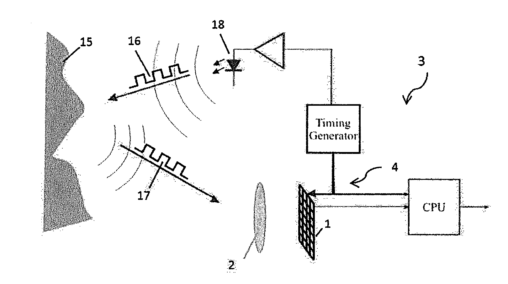
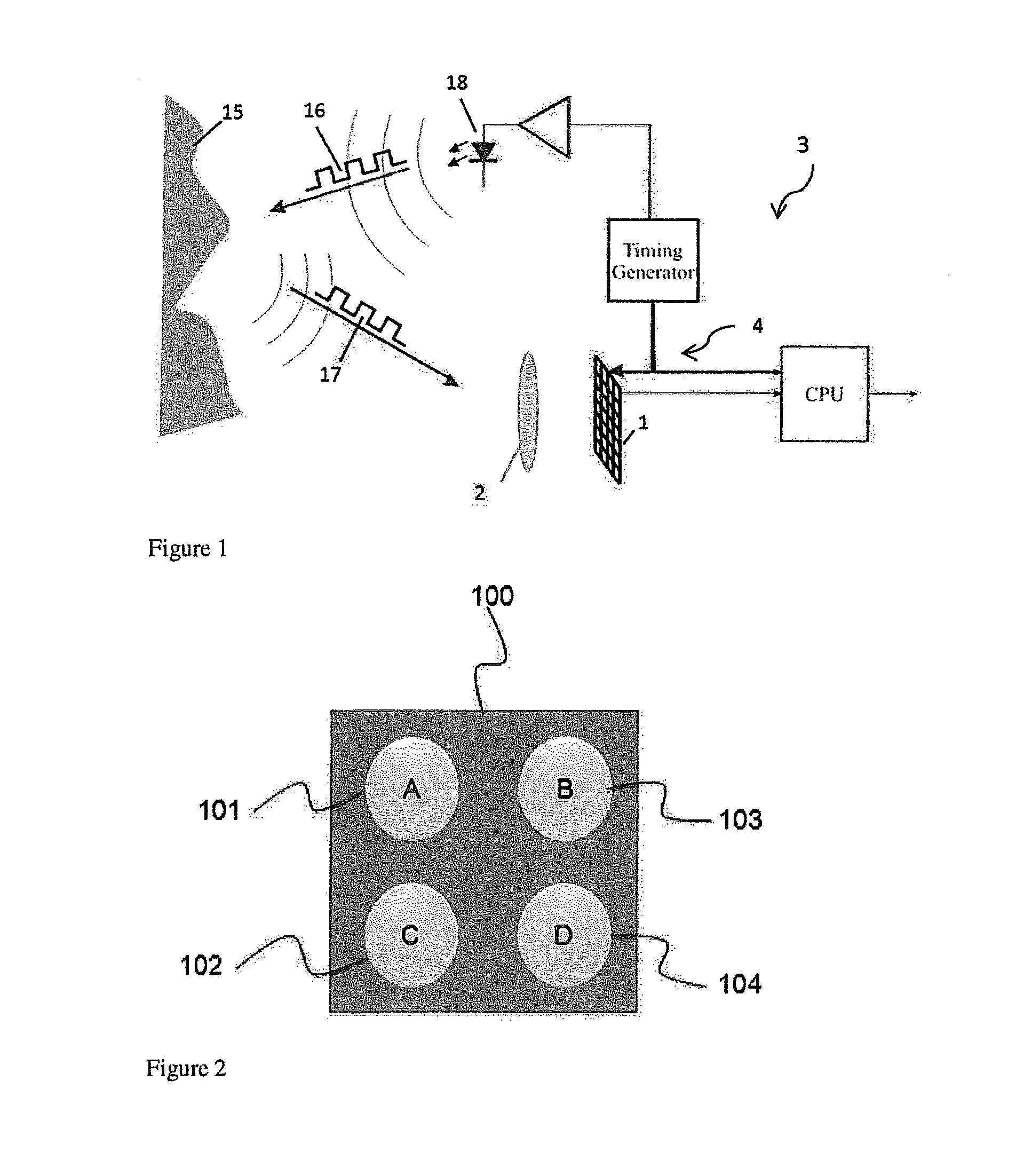
[0029]As illustrated by FIG. 1, a conventional TOF camera system comprises one TOF sensor 1 and its associated optical means 2 (e.g. a lens), an illumination unit 18 for illuminating the scene 15 with respect to the TOF principle specifications, and an electronic circuitry 4 for at least driving the illumination unit and the TOF sensor. The light is usually in the infra-red wavelength domain and comprises periodically modulated pulses 16 emitted toward the scene. The TOF sensor and its associated optical means are designed to enable the capture of the emitted modulated light that is reflected back from the scene. One option for determining distance in...


PUM


Abstract

The invention relates to a TOF camera system comprising several cameras, at least one of the cameras being a TOF camera, wherein the cameras are assembled on a common substrate and are imaging the same scene simultaneously and wherein at least two cameras are driven by different driving parameters.

Description

FIELD OF THE INVENTION[0001]The present invention relates to Time-Of-Flight (TOF) range imaging systems, namely TOF camera systems. In particular, the aim of the present invention is to provide a 3D image of a scene of high quality.BACKGROUND OF THE INVENTION[0002]Computer vision is a growing research field that includes methods for acquiring, processing, analysing, and understanding images. The main driving idea in that field is to duplicate the abilities of the human vision system by electronically perceiving and understanding images of a scene. Notably, one theme of research in computer vision is the depth perception or, in other words, the three-dimensional (3D) vision.[0003]For human beings, the depth perception is originated from the so-called stereoscopic effect by which the human brain fuses two slightly different images of a scene captured by the two eyes, and retrieves, among others, depth information. Moreover, recent studies have shown that the capacity to recognize obje...

Claims


Application Information

Patent Timeline
Patent Type & Authority Applications(United States)
IPC IPC(8): H04N13/02H04N13/00G01S17/86G01S17/894H04N13/128
CPCH04N13/025H04N13/0242H04N13/0271H04N2013/0081H04N13/0246H04N13/0022H04N13/0018H04N13/0257H04N13/207H04N13/128H04N13/271G01S17/86G01S17/894H04N13/239H04N25/41H04N13/257H04N13/236H04N13/218H04N23/80H04N13/243H04N13/246H04N13/25H04N13/122
Inventor VAN NIEUWENHOVE, DANIELTHOLLOT, JULIEN
Owner SONY DEPTHSENSING SOLUTIONS SA NV
Why Eureka
Try Eureka