
Printer

a printing machine and printing technology, applied in the field of printing machines, can solve the problems of continuous paper deviating out of the range determined, deteriorating printing quality, and often deviating from the range, so as to and ensure the printing quality of the printer

Active Publication Date: 2016-11-10
SATO HLDG CORP
View PDF1 Cites 5 Cited by
  • Summary
  • Abstract
  • Description
  • Claims
  • Application Information

AI Technical Summary

Benefits of technology

The present invention aims to provide a printing technique that ensures high printing quality of a printer. This is achieved through a design that prevents the print medium from deviating out of range determined by a guiding piece, which helps to ensure the print medium runs smoothly during the printing operation. Additionally, this design also prevents the print medium from running on the guiding piece when returning from back feeding, which helps to maintain the functionality of a damper portion and ensures the printing quality of the printer.

Problems solved by technology

This back feeding may cause the continuous paper to contact a bottom surface of a printer chassis, which leads to a slack.
In this case, since the continuous paper is positioned below a lower end of a width adjustment guiding portion, this causes the continuous paper to deviate out of range determined by the width adjustment guiding portion.
However, returning to a printing operation in this state causes the continuous paper to run on the width adjustment guiding portion, and to be fed in a state where a damper portion does not function.
This results in a printing position displaced off from a planned position and a thinned printing density, and ends up with deteriorated printing quality.
Especially in the case where a width of the continuous paper is short, the continuous paper often deviates from the width adjustment guiding portion.

Method used


Image

  • Printer
  • Printer
  • Printer

Examples


Embodiment Construction

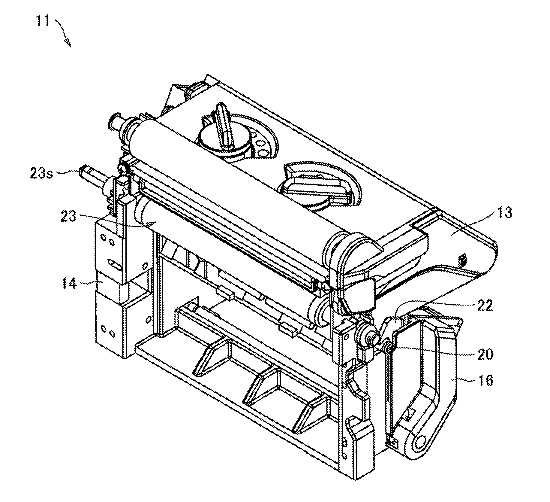
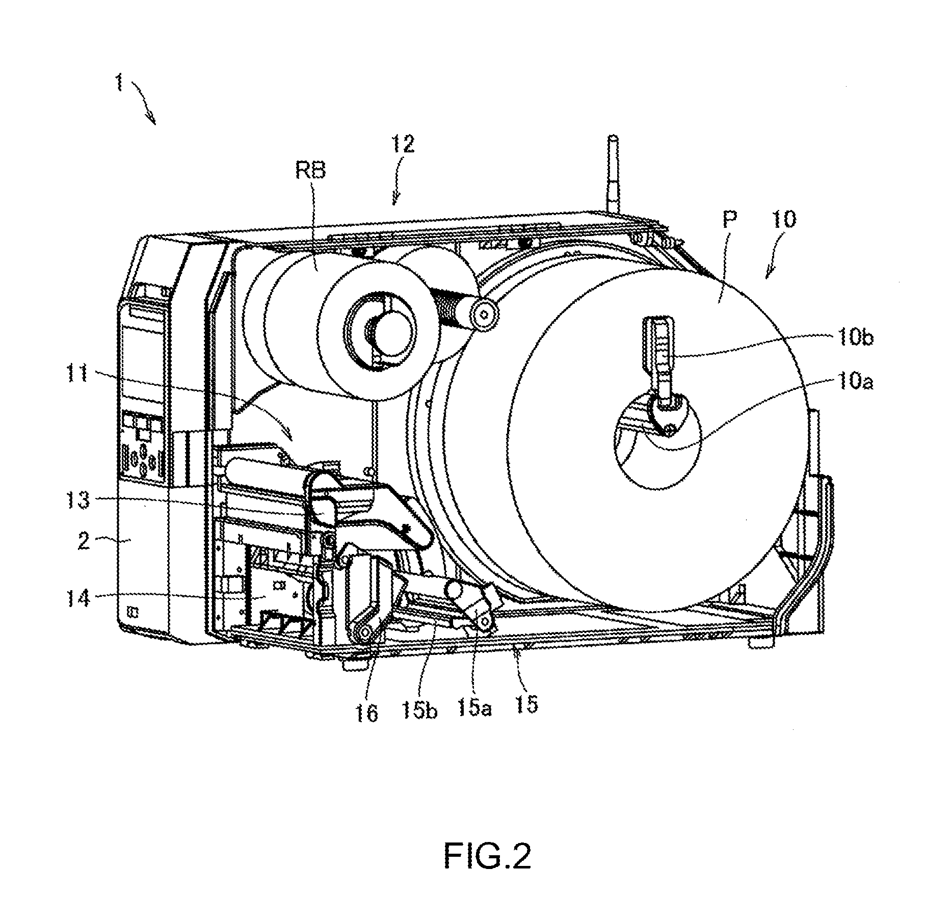
[0037]The following describes an embodiment as an example of the present invention in detail based on drawings. It should be noted that in the drawings to describe the embodiment, an identical reference numeral is basically attached to an identical component, and its repeated description is omitted.

[0038]A feed direction for printing a continuous paper (print medium), specifically a direction feeding the continuous paper from a paper sheet supply unit to a thermal head portion, is referred to as a printing direction, and if there is no specific description, an upstream in the feed direction is referred to as an upstream side in the printing direction, and the downstream in the feed direction is referred to as a downstream side in the printing direction.

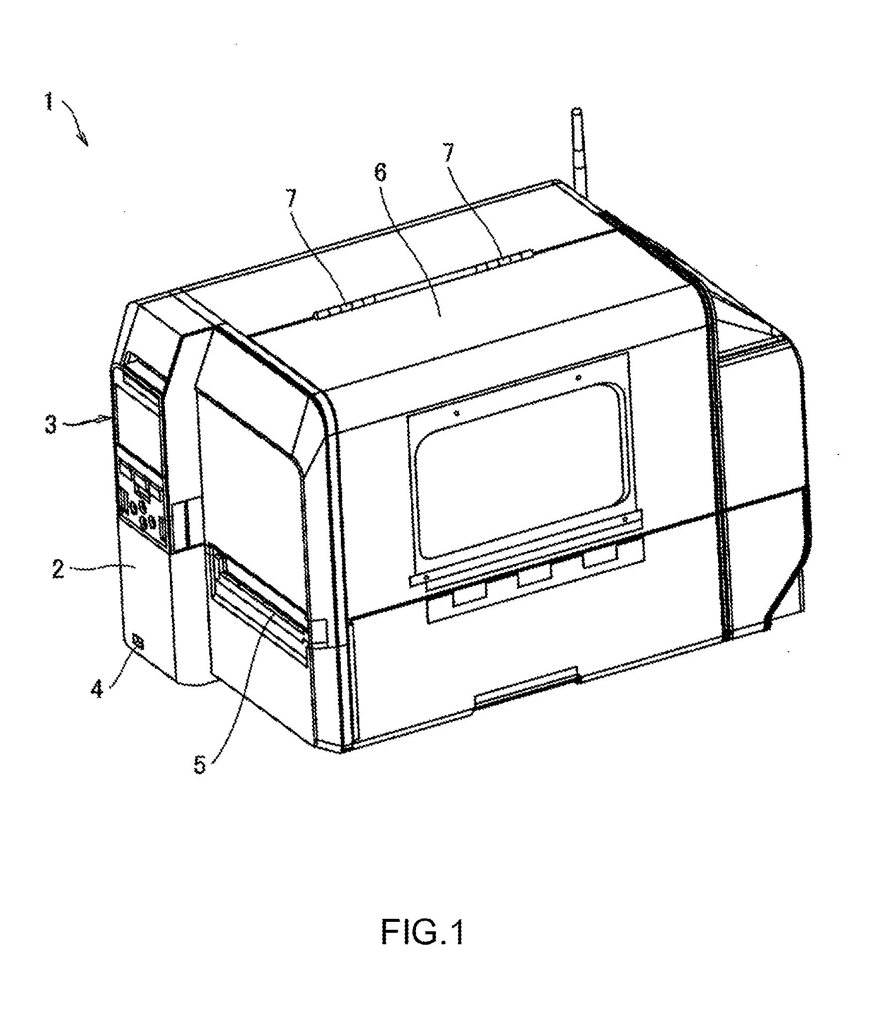
[0039]FIG. 1 is an overall perspective view of an appearance of a printer according to the embodiment.

[0040]A printer 1 according to the embodiment has, for example, a label printing function, which prints information such as a charac...


PUM


Abstract

In a printer for printing on a label of a continuous paper in a middle of feeding the continuous paper unwound from a paper sheet supply unit, while a depressed portion is disposed below a damper portion, a width adjustment guiding portion, which contacts an outer edge in a width direction of the continuous paper to guide a feed of the continuous paper, is disposed on a lower portion of the damper portion such that the lower end portion of the width adjustment guiding portion is positioned within the depressed portion.

Description

TECHNICAL FIELD[0001]The present invention relates a printer, for example, a printer having a label printing function that prints desired information, such as a character, a sign, a diagram, a barcode, or similar information, on a label or a similar printing medium.BACKGROUND ART[0002]A label printer is a printer having a function that, for example, while unwinding a rolled continuous paper to feed the continuous paper in a sheet-shape, prints desired information on a label of the continuous paper.[0003]At a printing unit of this label printer, a thermal head portion, which prints on the label, and a platen roller portion, which feeds the continuous paper, are disposed in a mutually opposing state.[0004]Between a paper sheet supply unit and the thermal head portion at the printing unit, a damper portion, which gives tension to the continuous paper, is installed. In a lower portion of this damper portion, a width adjustment guiding portion, which contacts a side edge in a width direc...

Claims


Application Information

Patent Timeline
Patent Type & Authority Applications(United States)
IPC IPC(8): B41J11/00
CPCB41J11/0045B41J15/042B41J15/046B41J15/16
Inventor KOKUTA, HIROSHI
Owner SATO HLDG CORP
Learn More