Airplane Cabin Panoramic View System

a panoramic view and cabin technology, applied in the field of aircraft cabin panoramic view systems, can solve the problems of limited visibility outside the aircraft, and limited window size of the cabin

a panoramic view and cabin technology, applied in the field of aircraft cabin panoramic view systems, can solve the problems of limited visibility outside the aircraft, and limited window size of the cabin

US20160325836A1Active Publication Date: 2016-11-10THE BOEING CO

Image

  • Airplane Cabin Panoramic View System
  • Airplane Cabin Panoramic View System
  • Airplane Cabin Panoramic View System

Examples


Embodiment Construction

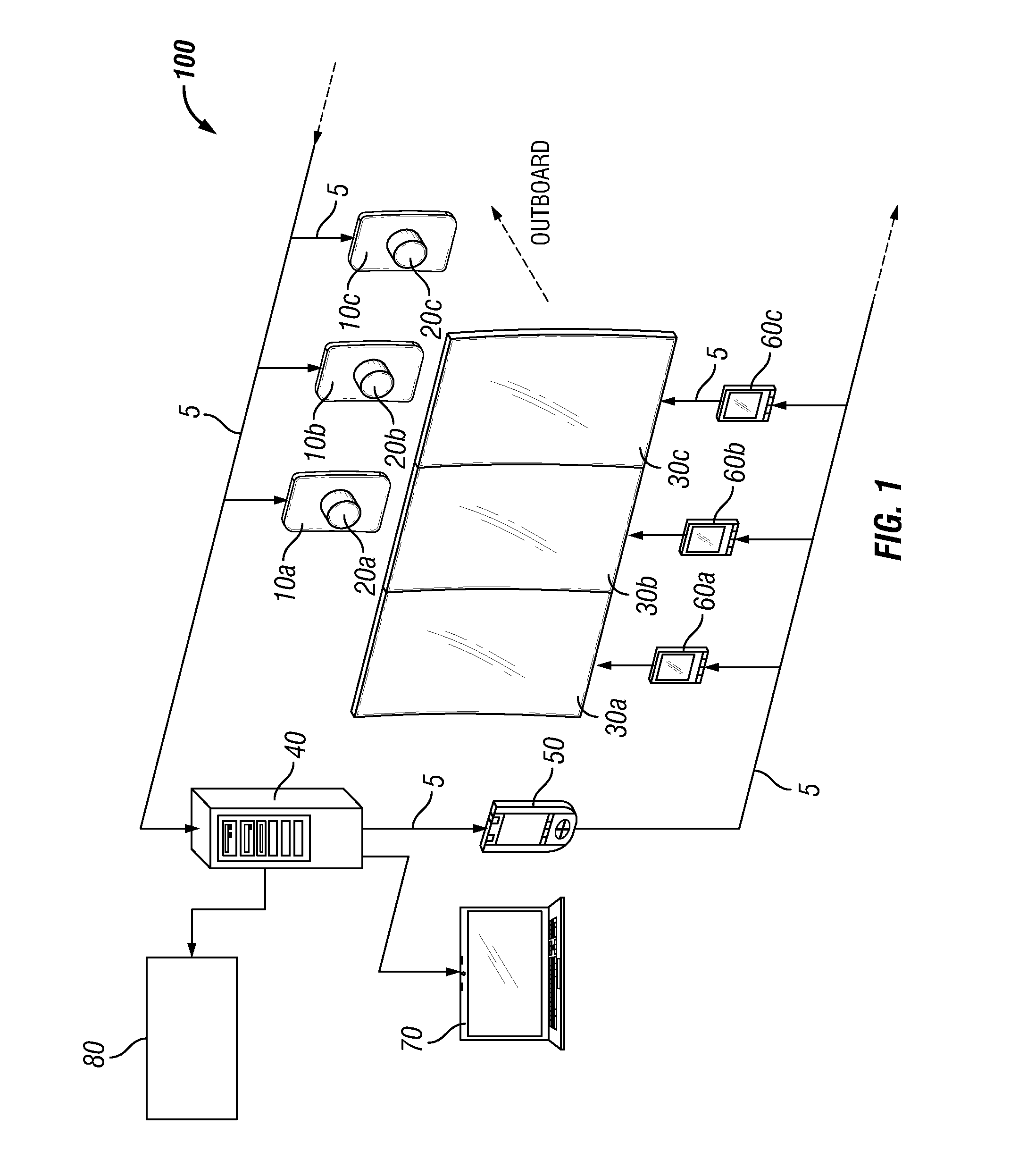
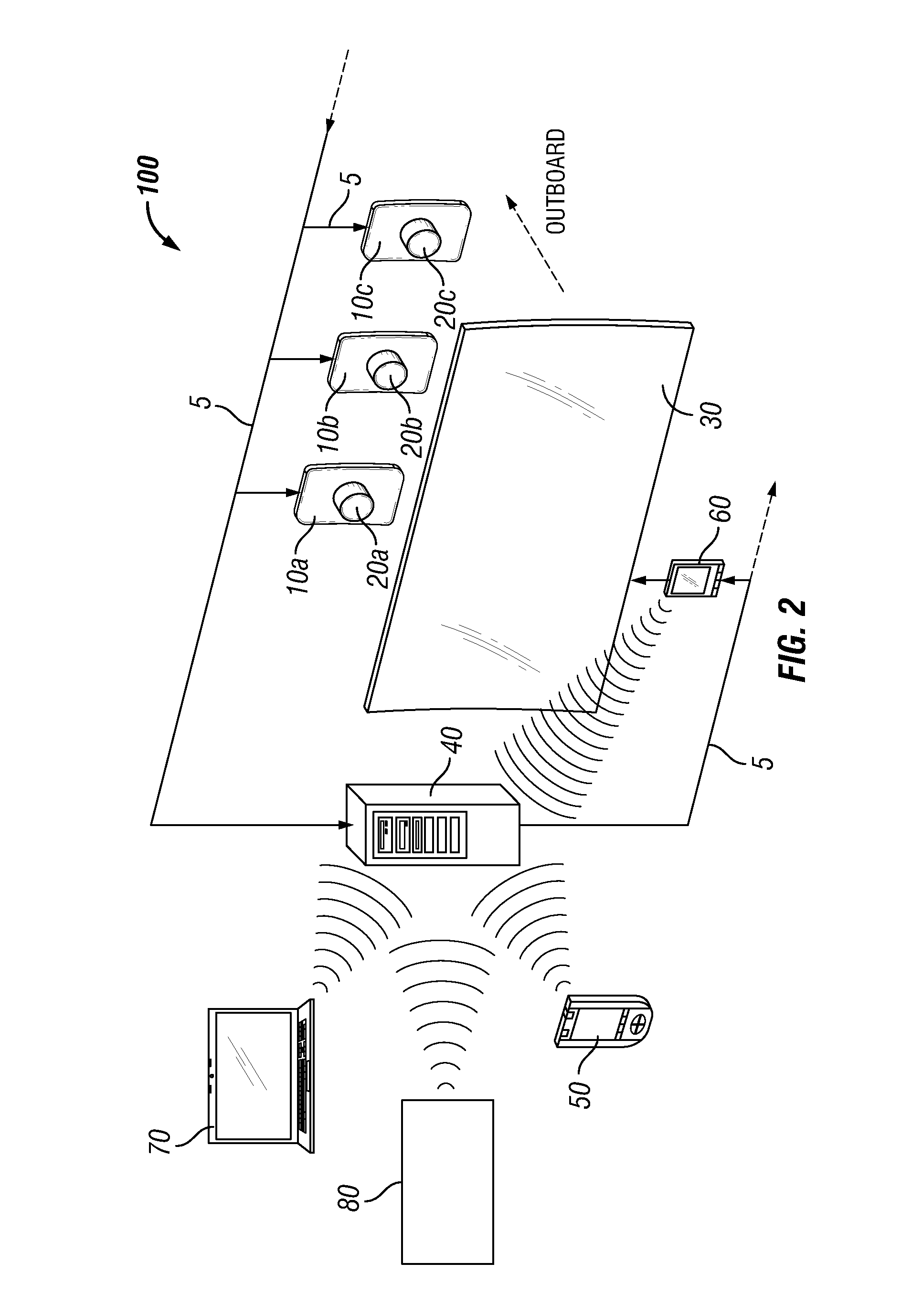
[0021]FIG. 1 shows a schematic of an aircraft display system 100 that may be used to display a panoramic view of an area that is outside of the aircraft. The system includes a plurality of window plugs 10 that are configured to fit within existing windows of an aircraft. Each plug 10 may include a camera 20 that is positioned within the plug 10 so as to permit images and / or video exterior to the aircraft to be captured by the camera 20 as indicated by the arrow labeled outboard. The system may include a first window plug 10a including a first camera 20a, a second window plug 10b including a second camera 20b, and a third window plug 10c including a third camera 20c. The number of window plugs 10 and cameras 20 shown in FIG. 1 are for illustrative purposes only and may be varied as would be appreciated by one of ordinary skill in the art having the benefit of this disclosure. As described below, the window plugs 10 are positioned within windows of an aircraft such that the cameras 20...


PUM


Abstract

A system and method for displaying on a display inside of an aircraft a panoramic view of a view outside the aircraft. The system includes a window plug configured to fit into a window of an aircraft. The window plug includes a camera positioned to capture video outside of the aircraft and a display positioned over the window plug. The camera and display are connected to a processor to display the captured video on the display. The system may include a control panel that controls the operation of the camera and display. A device may be used to control pan and zoom features of the camera. A plurality of cameras may be connected to the processor, which may combine the captured videos from the plurality of cameras to display a single panoramic video on a single display or a plurality of displays. The combined video may be a 3D video.

Description

FIELD OF THE DISCLOSURE[0001]The embodiments described herein relate to a system and method for capturing and displaying a panoramic view of the environment outside of an aircraft to the passengers inside the aircraft.BACKGROUNDDescription of the Related Art[0002]Aircraft are presently designed with windows in the passenger cabins to permit passengers to view outside of the aircraft. However, the windows in the cabins are typically limited in size because of structural constraints. The small size of cabins windows may limit visibility outside of the aircraft to passengers seated in window seats even though most passengers would like to see outside of the aircraft during the duration of a flight. The size of the windows of a cabin is limited due to structural constraints on the aircraft, thus limiting the view outside of the cabin.[0003]Recently a panoramic window has been designed in an attempt to increase the viewing area outside of a cabin. However, the implementation of these wid...

Claims


Application Information

Patent Timeline
10 Nov 2016
Publication
US20160325836A1
IPC
B64D11/00; H04N5/232; B64C1/14; H04N7/18
CPC
B64D11/0015; H04N7/183; B64D2011/0061; B64C1/14; H04N5/23238; H04N13/282; G06F3/00; G06F3/005
Inventors
TEO, DAVID