Working posture holding device

a technology of holding device and working posture, which is applied in the direction of chairs, applications, manufacturing tools, etc., can solve the problem that the chair does not sufficiently remove the physical burden of the surgeon

Inactive Publication Date: 2016-11-17
PANASONIC CORP
View PDF3 Cites 9 Cited by
  • Summary
  • Abstract
  • Description
  • Claims
  • Application Information

AI Technical Summary

Benefits of technology

[0011]when the locking mechanism sets the leg part to be in the locked state, the lower back holding part holds a lower back of the user to hold a standing posture of the user and, when the locking mechanism sets the leg part to in the variable state, the user is able to walk.
[0012]According to the working posture holding device of this disclosure, when the locking mechanism sets the leg part to be in the “locked” state, the lower back holding part holds the lower back of the user and thereby holds the standing posture of the user that continues for a long time and, when the locking mechanism sets the leg part to be in the “variable” state, the user can walk.

Problems solved by technology

In this case, though a simple chair may be used, such a chair does not sufficiently remove the physical burden of the surgeon because of the restriction on the location to place the chair and of the case where the surgeon needs to move during a surgical operation.

Method used


Image

  • Working posture holding device
  • Working posture holding device
  • Working posture holding device

Examples


first embodiment

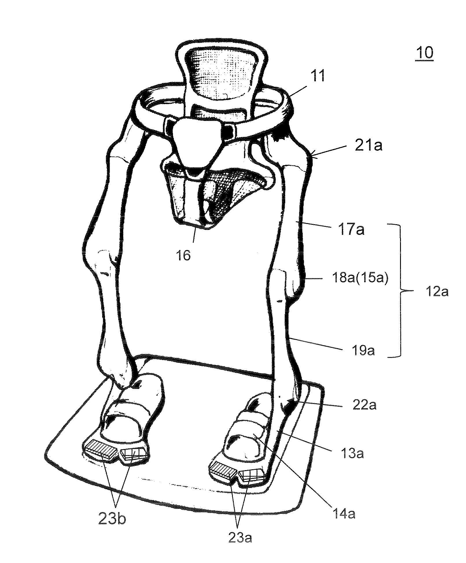
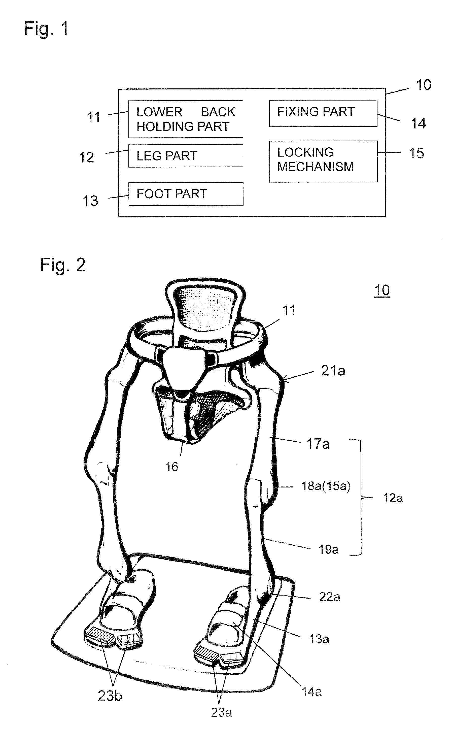
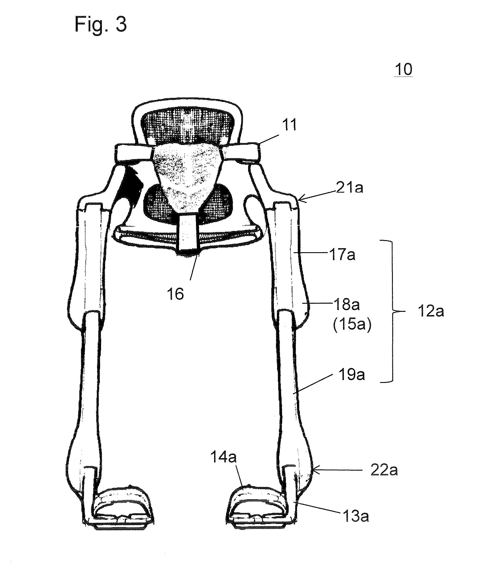
[0037]FIG. 1 is a block diagram of a configuration of the working posture holding device 10 according to the first embodiment. FIG. 2 is a perspective view of an overview of the working posture holding device 10 according to the first embodiment. FIG. 3 is a front view of the working posture holding device 10 of FIG. 2. FIG. 4 is a side view of the working posture holding device 10 of FIG. 2. FIG. 5 is a schematic view of an example where a user wears the working posture holding device 10 of FIG. 2.

[0038]The working posture holding device 10 according to the first embodiment includes a lower back holding part 11 that holds the lower back of a user, leg parts 12, 12a, and 12b that support the lower back holding part 11, foot parts 13, 13a, and 13b that are connected to the leg parts 12, 12a, and 12b, and that contact the ground to support the overall apparatus, fixing parts 14, 14a, and 14b that fix the leg parts 12, 12a, 12b, and the user to each other, and locking mechanisms 15, 15...

second embodiment

[0057]FIG. 6 is a perspective view of an overview of the working posture holding device 30 according to the second embodiment.

[0058]The working posture holding device 30 according to the second embodiment differs from the working posture holding device 10 according to the first embodiment in a comparison therebetween in that a saddle used in, for example, a bicycle is used as the saddle 36 and that a disc brake type locking mechanism 35a is disposed in a knee part 38a.

[0059]The working posture holding device 30 can easily be manufactured by using the saddle used in a bicycle or the like as the saddle 36 as above. The working posture holding device 30 can easily be manufactured and the knee part 38a can reliably be locked by using the disc brake type locking mechanism 35a.

third embodiment

[0060]FIG. 7 is a schematic view of a configuration of the leg part 32a of the working posture holding device according to the third embodiment.

[0061]The working posture holding device according to the third embodiment has the substantially same configuration as that of the working posture holding device 30 according to the second embodiment except the configuration of the leg part 32a. The leg part 32a of the working posture holding device according to the third embodiment differs from the leg part 32a of the working posture holding device 30 according to the second embodiment in a comparison therebetween in that no knee part is disposed in the leg part 32a for the leg part 32a to be stretchable to enable the variation of the distance I between the lower back holding part 11 and the foot part 33a. For example, the distance I is varied by the stretching or the shortening of the stretchable part 43a from the leg part 32a. In this case, as depicted in FIG. 7, because the leg part 32a ...


PUM


Abstract

A working posture holding device (10) includes: a lower back holding part (11) that holds a lower back of a user; a leg part (12a) that supports the lower back holding part, the leg part being rotatably connected to the lower back holding part, the leg part extending along a leg region of the user; a foot part (13a) that is connected to the leg part, the foot part contacting a ground to support the overall working posture holding device; a fixing part (14a) that fixes the leg part and the user to each other; and a locking mechanism (15a) that switches a state of the leg part between a “variable” state where a distance between a connection part to the lower back holding part and a connection part to the foot part is variable, and a “locked” state where the distance is fixed.

Description

TECHNICAL FIELD[0001]This disclosure relates to a working posture holding device to be worn on a body of a user to hold his / her standing posture that continues for a long time.BACKGROUND ART[0002]A surgeon is traditionally forced to maintain his / her standing posture during a surgical operation that continues for a long time. In this case, though a simple chair may be used, such a chair does not sufficiently remove the physical burden of the surgeon because of the restriction on the location to place the chair and of the case where the surgeon needs to move during a surgical operation.[0003]A chair to be used during a surgical operation is known whose height is adjustable as shown in Japanese Patent Laid-Open Publication No. 52-44095 referred as Patent Document 1 while this chair can provide its adjustable height for a surgeon only in his / her sitting posture. This chair is therefore not different from any traditional chair in that the surgeon needs to leave the chair to work when the...

Claims


Application Information

Patent Timeline
Patent Type & Authority Applications(United States)
IPC IPC(8): A61B90/60A61H3/00A47C9/02A47C3/00B25J9/00
CPCA61B90/60A47C3/00B25J9/0006A47C9/025A61H2203/0406A61H2201/1628A61H2201/1633A61H2201/164A61H2201/165A61H3/00A61H2201/1215
Inventor NAKATANI, KAZUHIROKONISHI, MAKOTOFUJIMOTO, HIROMICHI
Owner PANASONIC CORP
Why Eureka
Try Eureka