
Steering wheel structure

a technology of steering wheel and horn block, which is applied in the direction of vehicle components, pedestrian/occupant safety arrangements, acoustic signal devices, etc., can solve the problem of restricted escape of horn block, and achieve the effect of easy check

Active Publication Date: 2016-12-01
HONDA MOTOR CO LTD
View PDF8 Cites 10 Cited by
  • Summary
  • Abstract
  • Description
  • Claims
  • Application Information

AI Technical Summary

Benefits of technology

The present invention prevents a warning sound from being emitted when attaching a steering equipment component to a steering wheel by releasing the contact connection between the energizing portions when the component is pushed in for a predetermined reason. This allows for easy checking that the component is securely locked on the wheel.

Problems solved by technology

As a result, an escape of the horn block is restricted.

Method used


Image

  • Steering wheel structure
  • Steering wheel structure
  • Steering wheel structure

Examples


first embodiment

[0034]Firstly, a first embodiment shown in FIG. 1 to FIG. 4 will be described.

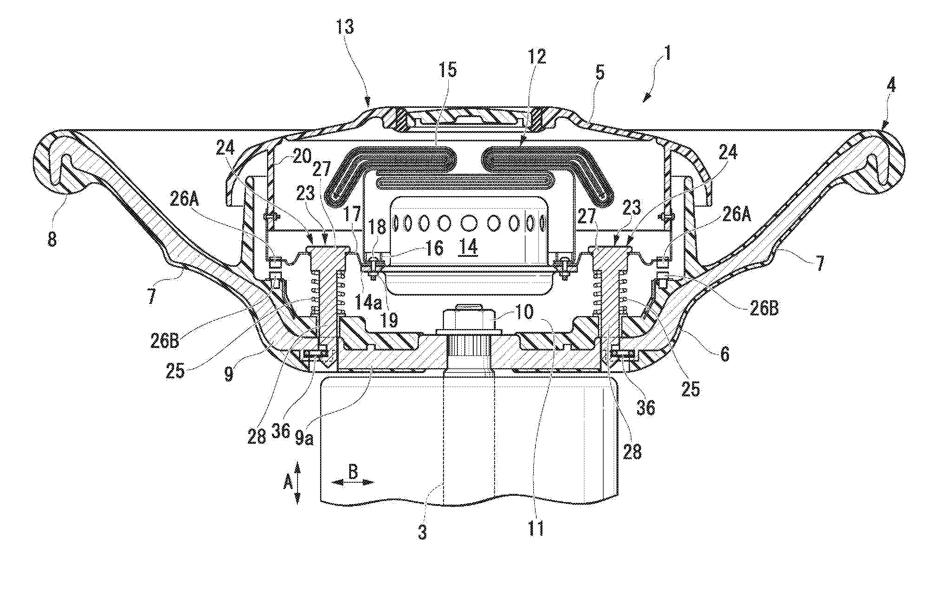
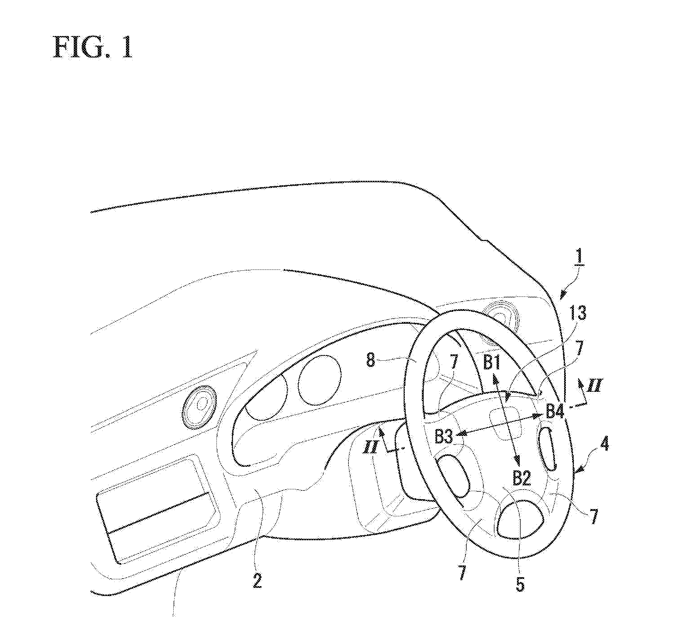
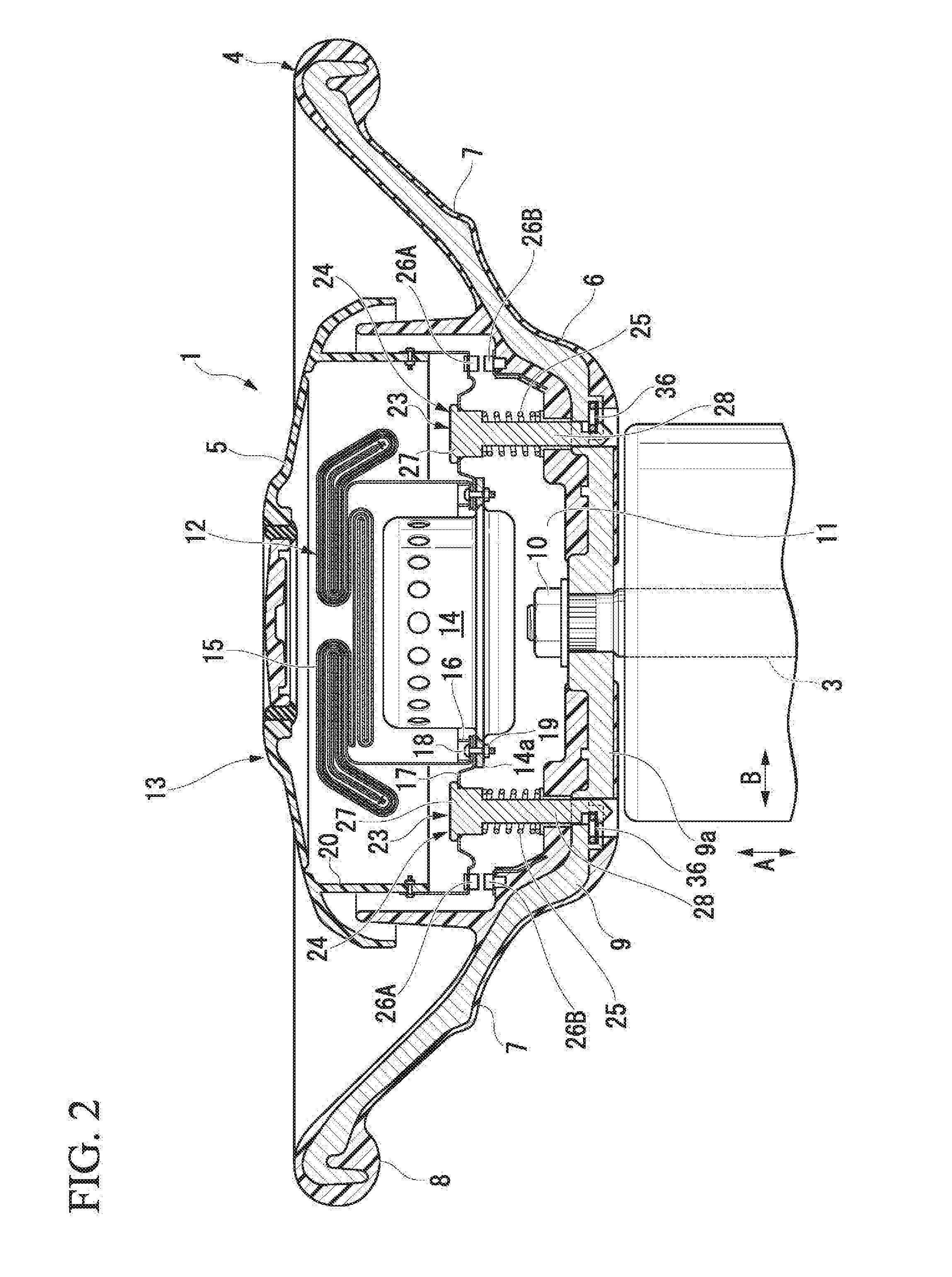
[0035]FIG. 1 is a diagram showing a driver's seat in an interior of a vehicle. FIG. 2 is a cross-sectional view of a steering wheel 1 that corresponds to a II-II cross-section of the driver's seat of FIG. 1.

[0036]As shown in these figures, in the steering wheel 1, a steering wheel main unit 4 that is held by a driver is attached to a front end of a steering shaft 3 that protrudes from an instrument panel 2 in a rearward direction on an interior side. A steering pad 5 as a horn operation portion is arranged in a central area of the steering wheel main unit 4.

[0037]Note that, in the following description, an axial direction means a longitudinal direction of the steering shaft 3 that is denoted with a direction of an arrow A in the figures unless otherwise specified. Similarly, orthogonal-to-axis directions mean directions orthogonal to the longitudinal direction of the steering shaft 3 that are denoted with ...

second embodiment

[0064]In a steering wheel structure of the second embodiment, there are provided a first floating support portion 23A and a second floating support portion 23B, which are slightly different in structure and function, between a horn block 13 and a steering wheel main unit 4.

[0065]In the first floating support portion 23A, a first attachment pin 24A in which a rubber elastic body 40 is interposed in a base end portion 31, is protrudingly provided through a horn block 13, and a steering wheel main unit 4 is provided with a first pin reception portion 27A that receives a front end portion of the first attachment pin 24A. In the second floating support portion 23B, a second attachment pin 24B, which is generally made of a conductive metal material, is protrudingly provided through the horn block 13, and the steering wheel main unit 4 is provided with a second pin reception portion 27B that receives a front end portion of the second attachment pin 24B.

[0066]Shaft portions 28 of the first ...


PUM


Abstract

This steering equipment component is retained on a steering wheel main unit (4) by a lock portion when, at the time of its attachment, pushed in the steering wheel main unit (4) by a predetermined stroke or longer. The steering wheel main unit (4) and the steering equipment component are each provided with an energizing portion, and the energizing portions energize a horn circuit (38) through their mutual contact. In attaching the steering equipment component, the energizing portions are configured to be in contact connection to each other until the steering equipment component is pushed in by the predetermined stroke or longer, and the contact connection between the energizing portions is configured to be interrupted when the steering equipment component is pushed in by the predetermined stroke or longer.

Description

TECHNICAL FIELD[0001]The present invention relates to a steering wheel structure of a vehicle.[0002]The present application claims priority based on Japanese Patent Application No. 2014-032062 filed on Feb. 21, 2014, the contents of which are incorporated herein by reference.BACKGROUND ART[0003]In a steering wheel of a vehicle, a steering equipment component such as a horn block is attached to a steering wheel main unit that is supported by a steering shaft.[0004]In attaching the steering equipment component, good workability and easiness with which it is attached to the steering wheel main unit are desired. Therefore, a variety of steering wheel structures are devised (for example, see Patent Document 1).[0005]In a steering wheel structure described in Patent Document 1, a horn block as a steering equipment component is protrudingly provided with attachment pins, and a steering wheel main unit is provided with a pin reception portion that receives a front end portion of the attachm...

Claims


Application Information

Patent Timeline
IPC IPC(8): B62D1/04B60Q5/00B60R21/203
CPCB62D1/04B60Q5/003B60R21/2037
Inventor OBAYASHI, YUYA
Owner HONDA MOTOR CO LTD
Learn More