Fishing Line Dispenser

a dispenser and fishing line technology, applied in the field of fishing and equipment, can solve the problems of common bulky apparatus, lack of space economy, and complex mechanical structure, and achieve the effect of preventing any undesirable slackening of fishing lin

Active Publication Date: 2016-12-15
RICHARDSON TERRY
View PDF0 Cites 29 Cited by
  • Summary
  • Abstract
  • Description
  • Claims
  • Application Information

AI Technical Summary

Benefits of technology

[0006]In a preferred embodiment, the “” bracket is composed of a length of round metal bar stock, preferably stainless steel, and suitably aluminum. The rigid attachments of the proximal ends of the cylindrical arm and the spindle arm to the “” bracket's column preferably comprise 90° bends in such bar. The instant invention's provision of such “” configured metal bar advantageously promotes materials and costs economy while enhancing both mechanical simplicity in line dispensing and facilitating compact storage of the device.
[0008]In the compact storage use of the instant inventive fishing line dispenser, the fisherman may pivot the “” bracket downwardly toward the base. Upon pivoting of the “” bracket into close proximity with the base, the dispenser maximizes space economy and may be stored within compact sales packaging or within a fishing equipment storage box.
[0010]Thereafter, the fisherman may attach an end of the spooled line to a fishing reel and may progressively transfer the fishing line from the spool to the fishing reel. During such transfer, sliding friction existing between the circular peripheral edges of the spool's disc shaped end walls and the floor of the concavity prevents any undesirable slackening of the fishing line between the reel and the spool.

Problems solved by technology

Such apparatus are commonly bulky, lacking in space economy, and often are mechanically complex.
Such apparatus are also commonly tedious and labor intensive in configuration for use, and in reconfiguration for storage, and such apparatus are typically lacking in materials and costs economies.

Method used


Image

  • Fishing Line Dispenser
  • Fishing Line Dispenser
  • Fishing Line Dispenser

Examples


Embodiment Construction

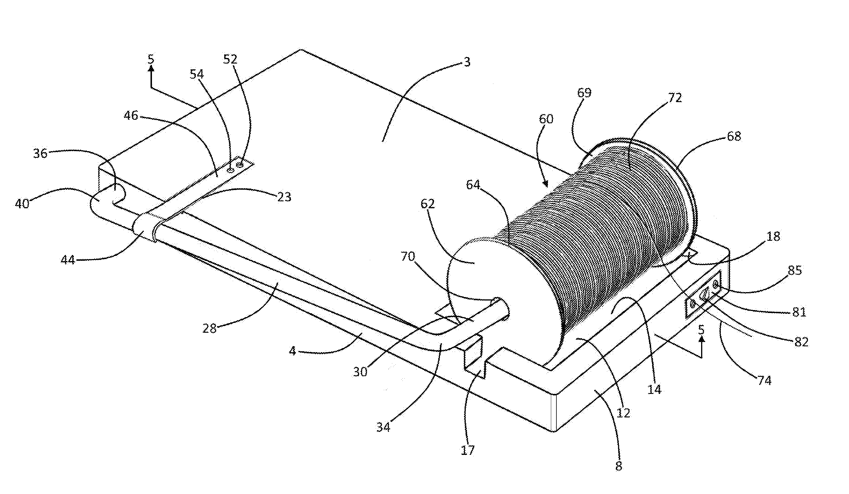
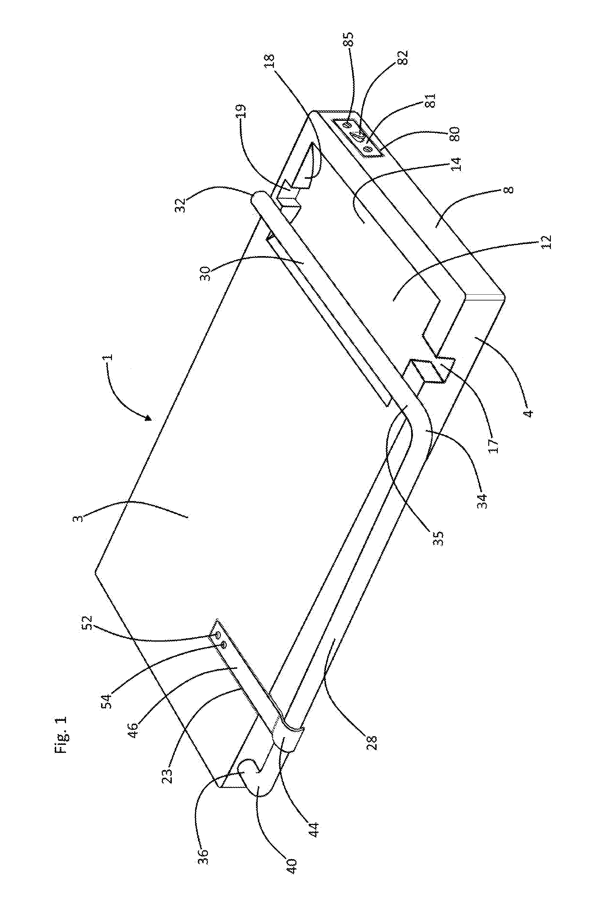
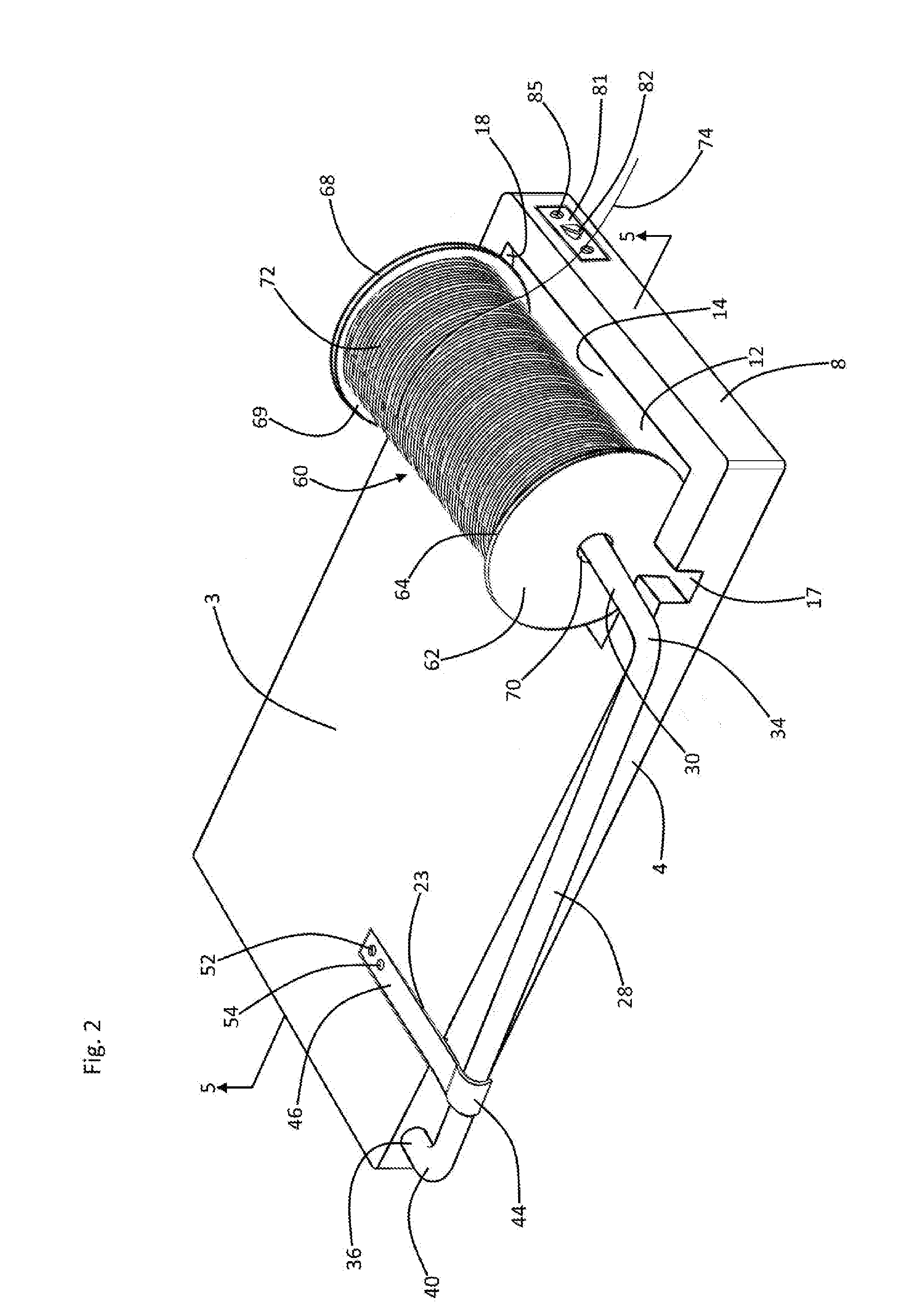
[0018]Referring now to the drawings and in particular simultaneously to Drawing FIGS. 1-3, and 5, a preferred embodiment of the instant inventive fishing line dispenser is referred to generally by Reference Arrow 1. The dispenser 1 preferably comprises a rectangular base component which is referred to generally by Reference Arrow 2. The base 2 has an upper surface 3 and has a lower surface which is preferably fabricated via an injection molding process to present a matrix of downwardly opening concavities 5 and stiffening ridges 7. The provision of such concavities advantageously promotes the invention's materials and cost economies objectives, and a bulk reduction objective. As an alternative to the injection molded base 2 represented in the drawings, the invention's base may suitably, though less desirably, comprise a solid wooden, plastic, or laminate composite slab. The base 2 further has a front end 8, a rear end 10, a lateral side 4, and an oppositely lateral side 6, the recta...


PUM


Abstract

A fishing line dispenser, the fishing line being wound about a spool having circular walls, and a bore, the dispenser including a base; a “” bracket including a column having front and rear ends, a cylindrical arm having a proximal end rigidly attached to the column's rear end, and having a spindle arm having a proximal end rigidly attached to the column's front end, the spindle arm being fitted for extension into the spool's bore; a pivot joint interconnecting the “” bracket and the base, the pivot joint having first and second halves, first half being positioned at the base's rear end, and the second half including the “” bracket's cylindrical arm; and a concavity positioned within the base for, upon the spindle arm's oppositely lateral extension into the spool's bore and upon downward pivoting of the “” bracket, receiving and frictionally engaging the spool's circular walls.

Description

FIELD OF THE INVENTION[0001]This invention relates to fishing and apparatus associated with the fishing arts. More particularly, this invention relates to apparatus adapted for assisting in transfers of bulk spooled fishing line onto fishing reels.BACKGROUND OF THE INVENTION[0002]Apparatus for assisting a fisherman with the task of transferring fishing line from a bulk spool to a fishing reel are known. Such apparatus are commonly bulky, lacking in space economy, and often are mechanically complex. Such apparatus are also commonly tedious and labor intensive in configuration for use, and in reconfiguration for storage, and such apparatus are typically lacking in materials and costs economies.[0003]The instant inventive fishing line dispenser solves or ameliorates the problems, deficits, and defects of prior art fishing line dispensers discussed above by incorporating within the fishing line dispenser a rigid pivoting “” bracket and base plate combination having multiple specialized ...

Claims


Application Information

Patent Timeline
Patent Type & Authority Applications(United States)
IPC IPC(8): A01K89/00B65H49/32
CPCA01K89/003B65H2701/355B65H49/321B65H49/205B65H49/325B65H59/04B65H75/32
Inventor RICHARDSON, TERRY
Owner RICHARDSON TERRY
Why Eureka
Try Eureka