

System and methods for reducing particulate matter emissions
- Summary
- Abstract
- Description
- Claims
- Application Information
AI Technical Summary
Benefits of technology
Problems solved by technology
Method used
Image

Examples
Embodiment Construction
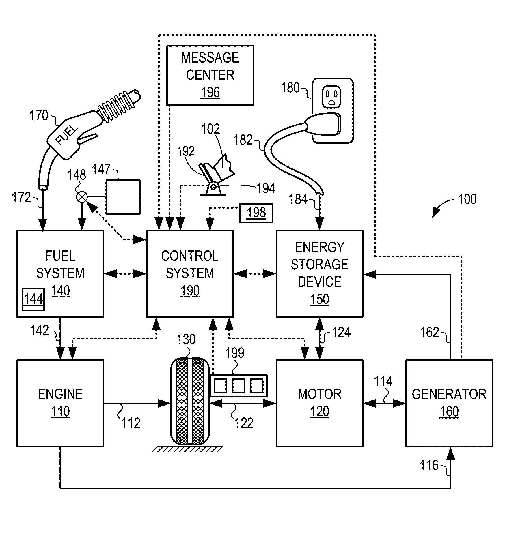
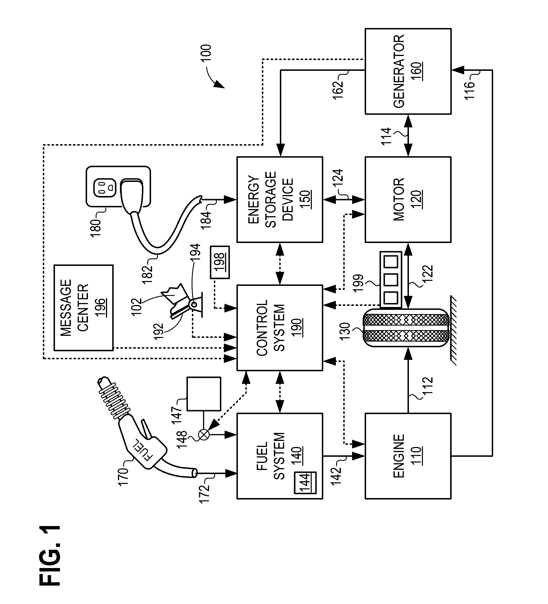
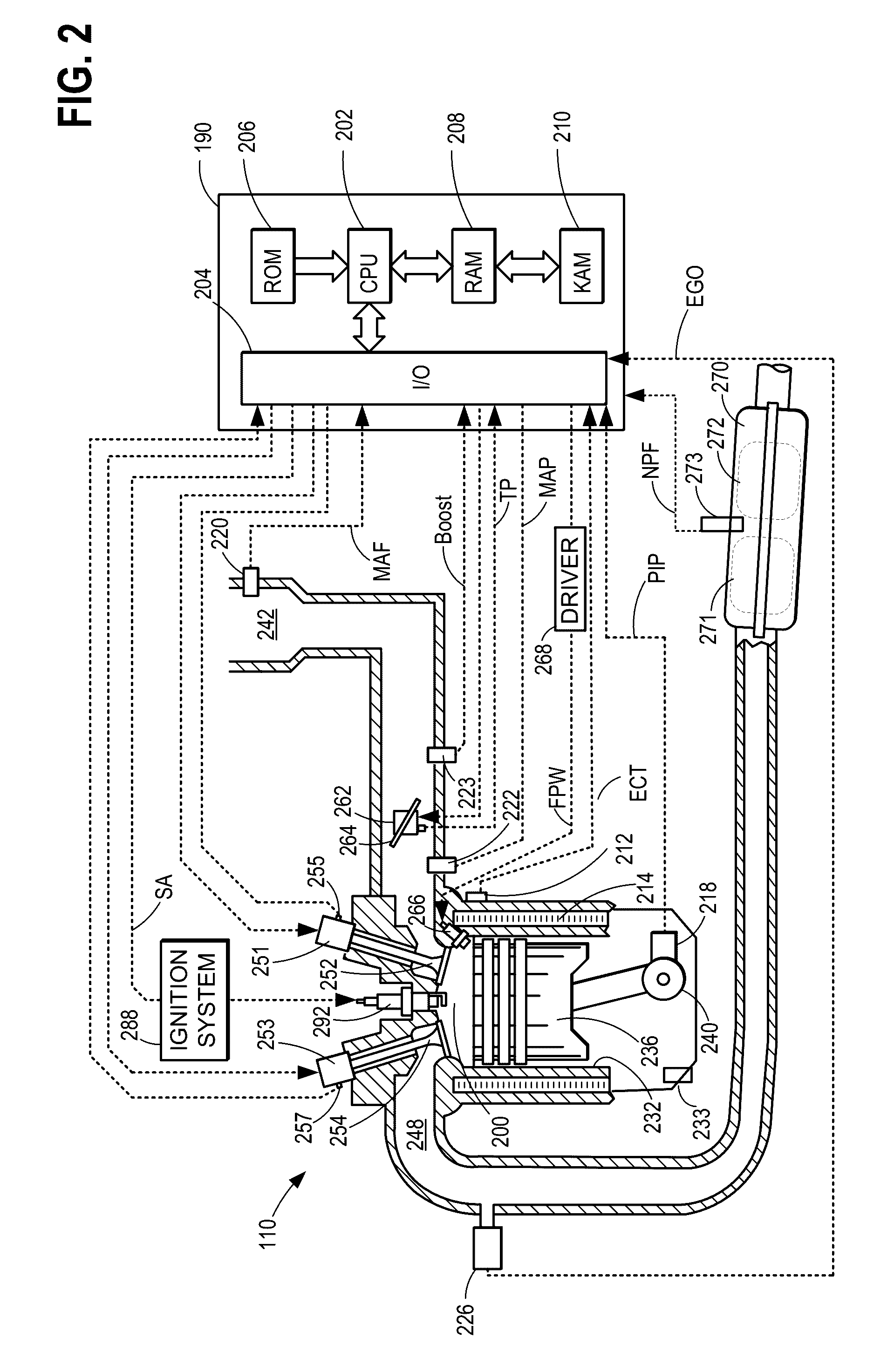
[0016]This detailed description relates to systems and methods for increasing the efficiency of an engine exhaust particulate filter in a vehicle propulsion system, such as the vehicle propulsion system of FIG. 1. In response to installation of a new exhaust particulate filter (as shown in FIG. 3) in an engine such as the engine of FIG. 2, fuel may be doped with an ash-producing additive. Combustion of the doped fuel produces ash, which deposits as an ash coating on the surfaces of the exhaust particulate filter, as shown in FIG. 6. In particular, FIGS. 4-5 illustrate how the ash coating on an exhaust particulate filter can increase the filtration efficiency of the filter as compared to a clean filter with no ash coating. A controller may perform executable instructions, as shown in the flow chart of FIG. 7, to dope the fuel with an ash-producing additive responsive to installation of a new exhaust particle filter or responsive to a new vehicle. In other cases, an operator may manua...
PUM
 Abstract
Description
Claims
Application Information