Air intake system for internal combustion engine

a technology of air intake system and internal combustion engine, which is applied in the direction of air intake for fuel, combustion-air/fuel-air treatment, machines/engines, etc., can solve the problems of engine control system, air leakage, throttle body movement relative to the intake manifold,

Inactive Publication Date: 2010-09-23
FORD GLOBAL TECH LLC
View PDF19 Cites 5 Cited by
  • Summary
  • Abstract
  • Description
  • Claims
  • Application Information

AI Technical Summary

Benefits of technology

[0008]According to a first aspect of the present invention, an air intake system for an internal combustion includes an intake manifold having an inlet flange. A throttle body is mounted to the inlet flange, with the throttle body including a valve body, and a throttle body flange...

Problems solved by technology

Because of the necessity for attaching various linkages and other devices to the throttle body, the throttle body is often subject to various pushing and pulling forces, some of which may cause the throttle body to move relative to the intake manifold.
This movement is undesirable because it may cause the throttle body's fasteners to loosen, thereby permitting air to leak through the joint extending between the throttle body and the intake manifold.
Such air leaks may be a problem because air leaking t...

Method used


Image

  • Air intake system for internal combustion engine
  • Air intake system for internal combustion engine
  • Air intake system for internal combustion engine

Examples


Embodiment Construction

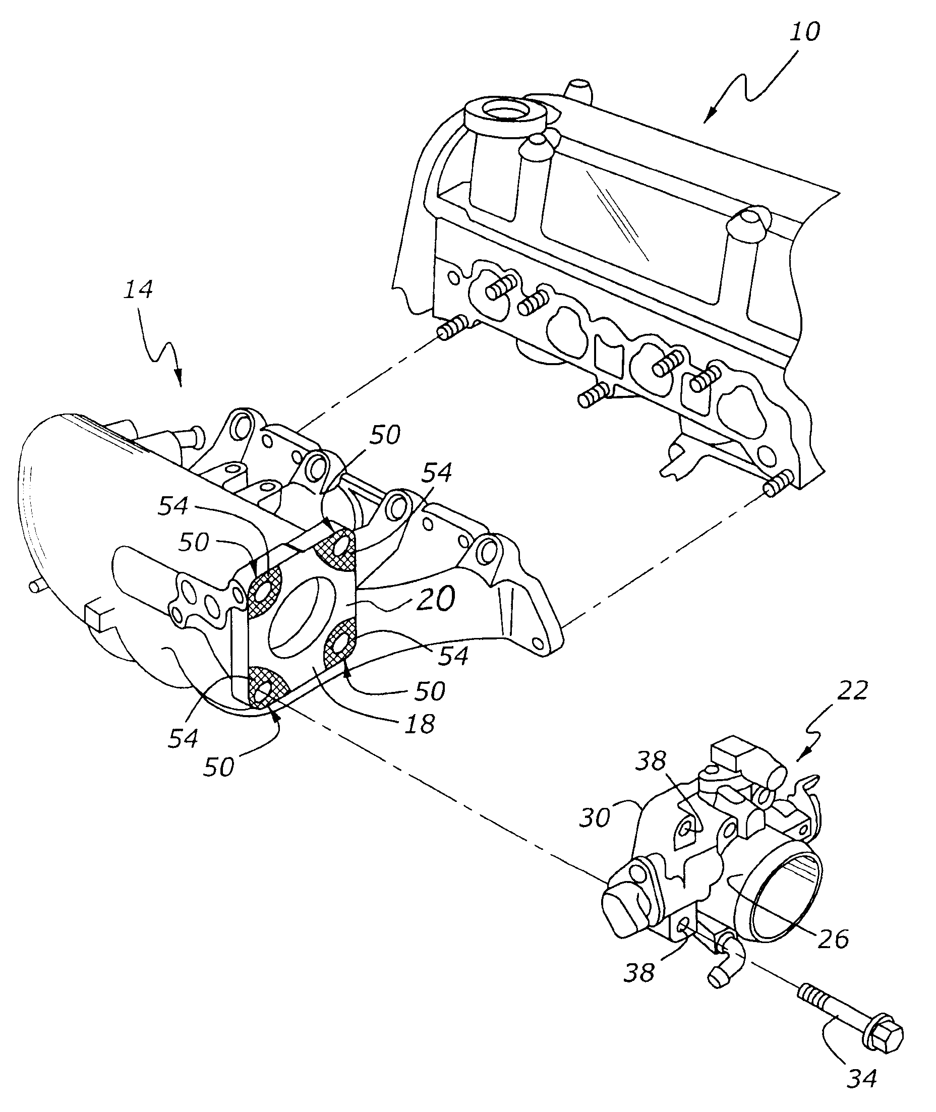
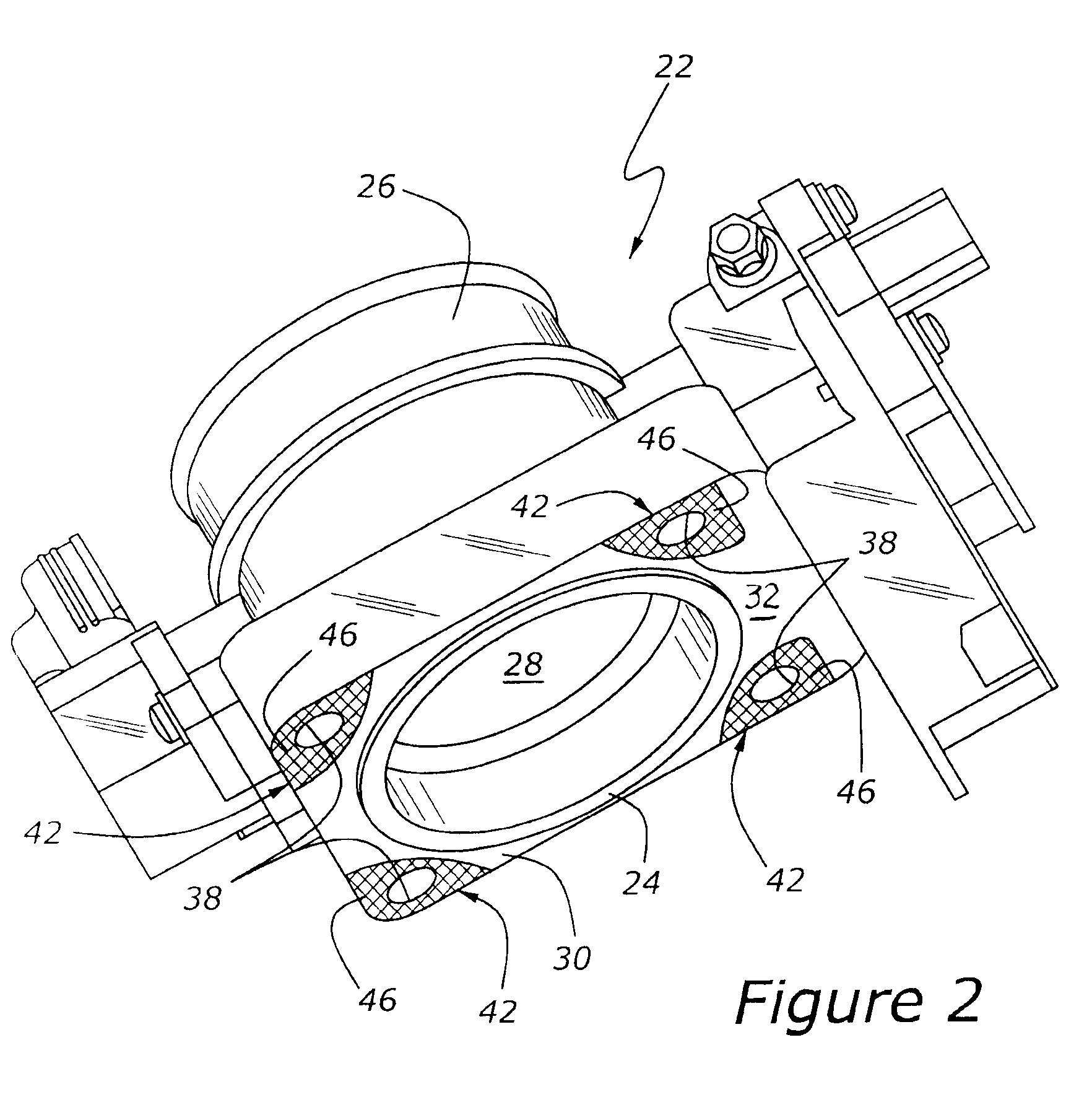
[0020]As shown in FIG. 1, an engine, 10, has an intake manifold, 14, with an inlet flange, 18. A throttle body, 22, is attached to intake manifold 14 with several threaded fasteners, 34. In the absence of the improvement according to the present invention, loss of tension from fasteners 34 may allow throttle body 22 to shift with respect to intake manifold 14.

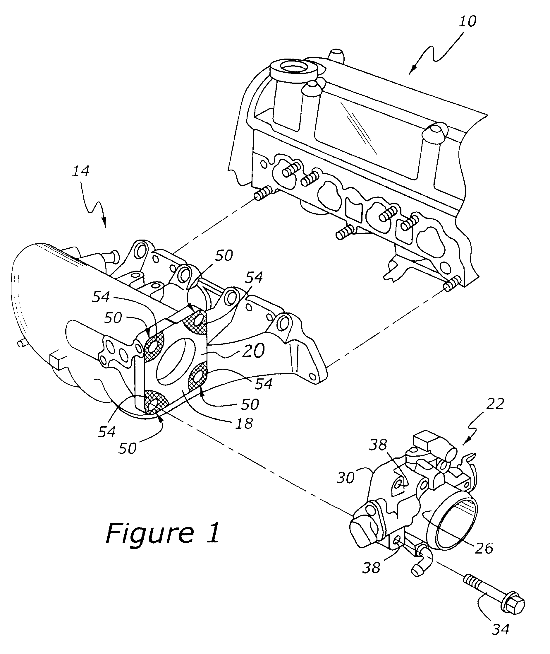
[0021]Intake manifold 14 and throttle body 22 are joined together at inlet flange 18, which, as noted above, is part of intake manifold 14, and usually one piece with intake manifold 14, and throttle body flange 30, which in a preferred embodiment, is one piece with valve body 26. Throttle body 22, as its name implies, has a rotatable throttle plate or valve 28, which is shown in FIG. 2.

[0022]FIG. 2 shows a number of friction promoting surfaces, 42, located on throttle body flange 30 in regions of inlet flange mating surface 32 which surround fastener bores 38. Fasteners 34 are inserted through fastener bores 38 for the purpose...


PUM

PropertyMeasurementUnit
Pressureaaaaaaaaaa
Frictionaaaaaaaaaa
Sliding frictionaaaaaaaaaa

Abstract

An air intake system for internal combustion engine includes an intake manifold having an inlet flange and a throttle body attached to inlet flange. The throttle body includes a matching throttle body flange which physically mates with the intake flange. A friction promoting surface having a positive coefficient of sliding friction is incorporated in at least one of the inlet flange and the throttle body flange so that sliding motion of the throttle body relative to the intake manifold will be resisted.

Description

CROSS REFERENCE TO RELATED APPLICATIONS[0001]None.BACKGROUND OF THE INVENTION[0002]1. Field of the Invention[0003]The present invention relates to an air intake system for providing combustion air to an internal combustion engine.[0004]2. Related Art[0005]Internal combustion engines typically use air intake manifolding to provide both fresh air and recirculated exhaust gases (EGR) to the engine's cylinders. Typically, a throttle body is attached to the intake manifold by threaded fasteners. Because of the necessity for attaching various linkages and other devices to the throttle body, the throttle body is often subject to various pushing and pulling forces, some of which may cause the throttle body to move relative to the intake manifold. This movement is undesirable because it may cause the throttle body's fasteners to loosen, thereby permitting air to leak through the joint extending between the throttle body and the intake manifold. Such air leaks may be a problem because air lea...

Claims


Application Information

Patent Timeline
IPC IPC(8): F02M35/10
CPCF02D9/1035F02D9/1085F02M35/10321F02M35/10144F02M35/10032
Inventor LOHR, JOHN CARL
Owner FORD GLOBAL TECH LLC
Why Eureka
Try Eureka