Block management for mass storage

a technology for managing blocks and mass storage, applied in the field of block management for mass storage, can solve the problems of time-consuming, performance hindrance, and much wasted memory space, and achieve the effect of improving system performance and improving manufacturing costs of the controller

Inactive Publication Date: 2007-05-24
MICRON TECH INC
View PDF1 Cites 5 Cited by
  • Summary
  • Abstract
  • Description
  • Claims
  • Application Information

AI Technical Summary

Benefits of technology

[0017] Briefly, an embodiment of the present invention includes An embodiment of the present invention includes a nonvolatile memory system comprising nonvolatile memory for storing sector information, the nonvolatile memory being organized into blocks with each block including a plurality of sectors, each sector identified by a logical block address and for storing sector information. A controller is coupled to the nonvolatile memory for writing sector information to the latter and for updating the sector information, wherein upon updating sector information, the controller writes to the next free or available sector(s) of a block such that upon multiple re-writes or updating of sector information, a plurality of blocks are substantially filled with sector information and upon such time, the controller rearranges the updated sector information in sequential order based on their respective logical block addresses thereby increasing system performance and improving manufacturing costs of the controller.

Problems solved by technology

The problem with this technique is that to move all of the sectors including current information to another new block is time-consuming and therefore a performance hindrance.
However, in this method, it is presumed that sectors are written in sequential order by the host, if this is not the case, there is much wasted memory space.
Obviously, this adversely affects system performance because every time there is a re-write of a sector, a new location within a free block is written thereto while the old information remains in the previous block until the system erases the latter.

Method used


Image

  • Block management for mass storage
  • Block management for mass storage
  • Block management for mass storage

Examples


Embodiment Construction

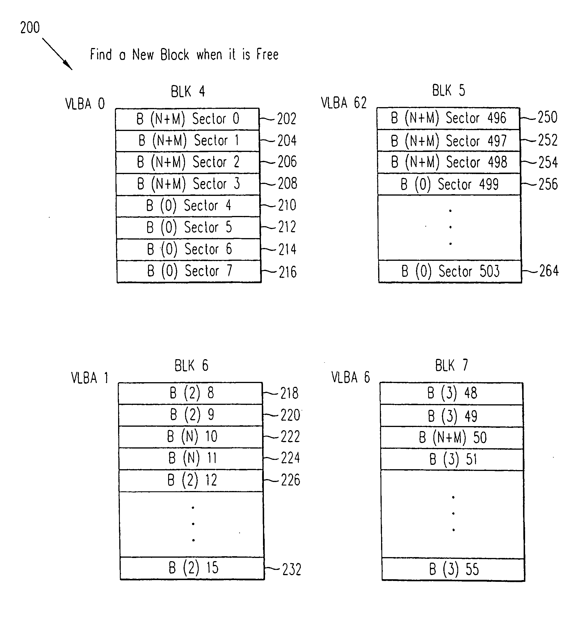
[0025] Referring now to FIG. 2, an example of the organization of information within nonvolatile memory devices is shown, in accordance with an embodiment of the present invention, to include M number of blocks 100, M being an integer with each block including sector information. As will be apparent shortly, the blocks 100 are temporary locations for storage of sector information commanded to be written by the host through a controller device. The blocks 100 are shown to include Block N, Block N+M and Block N+M−1, wherein N is also an integer number. The reason for the notation N is to emphasize that Block N and in fact Blocks N+M and N+M−1 can be any one of the blocks within a nonvolatile memory. In one embodiment of the present invention, four blocks are designated as the blocks within 100 and thus temporary locations for storing data or information received from the host but in other embodiments of the present invention, any number of blocks may be employed.

[0026] In one embodim...


PUM


Abstract

An embodiment of the present invention includes a nonvolatile memory system comprising nonvolatile memory for storing sector information, the nonvolatile memory being organized into blocks with each block including a plurality of sectors, each sector identified by a logical block address and for storing sector information. A controller is coupled to the nonvolatile memory for writing sector information to the latter and for updating the sector information, wherein upon updating sector information, the controller writes to the next free or available sector(s) of a block such that upon multiple re-writes or updating of sector information, a plurality of blocks are substantially filled with sector information and upon such time, the controller rearranges the updated sector information in sequential order based on their respective logical block addresses thereby increasing system performance and improving manufacturing costs of the controller.

Description

CROSS REFERENCE TO RELATED APPLICATIONS [0001] This application is a continuation of U.S. patent application Ser. No. 10 / 455,550, filed on Jun. 4, 2003 and entitled “Block Management For Mass Storage”, which is a continuation-in-part of my U.S. patent application Ser. No. 09 / 620,544, filed on Jul. 21, 2000 and entitled “Moving Sectors Within a Block of Information In a Flash Memory Mass Storage Architecture”, the disclosure of which is incorporated herein by reference as though set forth in full.BACKGROUND OF THE INVENTION [0002] 1. Field of the Invention [0003] The present invention relates generally to methods and apparatus for improving the performance of file management within nonvolatile memory devices and particularly to increasing the speed of writing or storing information to such nonvolatile memory devices. [0004] 2. Description of the Prior Art [0005] Various prior art methods and techniques were used to manage files, i.e. store data and read back data, within nonvolatile ...

Claims


Application Information

Patent Timeline
Patent Type & Authority Applications(United States)
IPC IPC(8): G06F12/00G11C8/12G11C16/08
CPCG06F12/0246G11C8/12G11C16/08
Inventor ESTAKHRI, PETRO
Owner MICRON TECH INC
Why Eureka
Try Eureka