Tread thickness measuring method

a technology of thickness measurement and measuring method, which is applied in the direction of instruments, specific gravity measurement, transportation and packaging, etc., can solve the problem of change in magnetic flux in the detection coil, and achieve the effect of greater precision

Active Publication Date: 2014-10-23
BRIDGESTONE CORP
View PDF1 Cites 5 Cited by
  • Summary
  • Abstract
  • Description
  • Claims
  • Application Information

AI Technical Summary

Benefits of technology

[0014]According to this aspect, ultrasonic waves of the same strength can be propagated to the tread surface by keeping a consta

Problems solved by technology

This will cause a change in the ma

Method used


Image

  • Tread thickness measuring method
  • Tread thickness measuring method
  • Tread thickness measuring method

Examples


Embodiment Construction

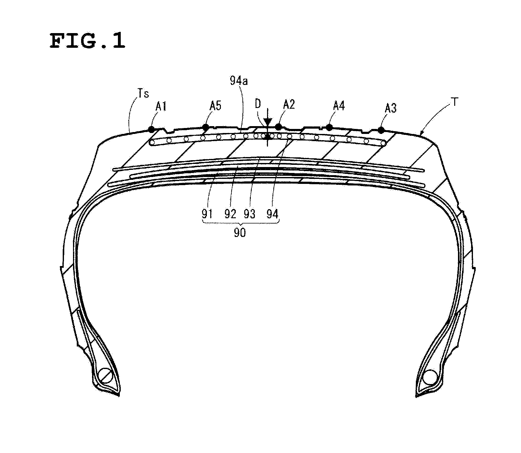
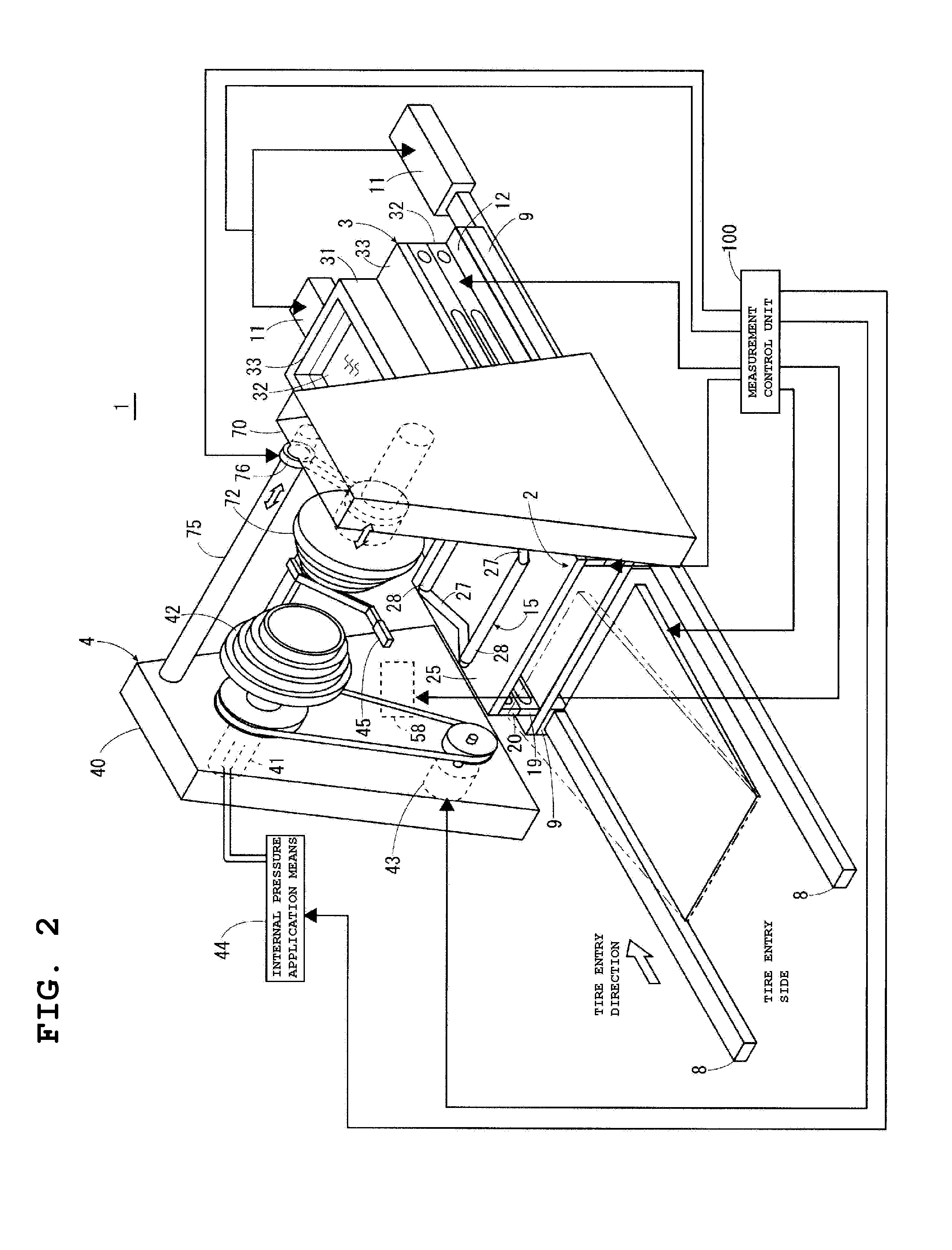
[0036]FIG. 1 is a cross-sectional view of a tire T which is subjected to a tread thickness measurement. FIG. 2 is a structural illustration of a tread thickness measuring apparatus 1.

[0037]A description is first given of the structure of a tire T of which the tread thickness D is measured with a tread thickness measuring apparatus 1 according to the present invention. The tire T to be subjected to a tread thickness measurement is a used tire, for instance. And, as shown in FIG. 1, the tire T has a belt layer 90, consisting of a plurality of belts 91 to 94, in the tread region. The belt layer 90 is constituted by the belts 91 to 93, which are located in radially inner positions of the tire, and the belt 94, which is located in a radially outermost position of the tire. The belts 91 to 93 are steel belts made of steel cords, whereas the belt 94 is a fiber belt made of non-metallic fiber cords. The tread thickness D according to the present embodiment is the distance from the tread sur...


PUM


Abstract

A method for measuring the tread thickness from the radially outermost belt surface within a tire to the tread surface accurately by ultrasonic measurement whatever the type of belt material is. The method includes the steps of measuring a profile of the tread surface, identifying the bottom positions of circumferentially extending grooves from the profile measured, estimating the depths from the groove bottoms to the belt surface from the identified groove bottoms and pre-created tire design data, predicting thicknesses by calculating predicted thicknesses from the tread surface to the belt surface from the relationship between the thicknesses from the identified groove bottoms to the tread surface in the profile and the estimated depths from the groove bottoms to the belt surface, and setting amplification factors for received reflected waves according to a reflection factor-thickness data map prepared beforehand in correspondence to the predicated thicknesses.

Description

BACKGROUND OF THE INVENTION[0001]1. Field of the Invention[0002]The present invention relates to a tread thickness measuring method and, in particular, to a method of measuring the tread thickness from the belt surface located in a radially outer position within a tire to the tread surface.[0003]2. Description of the Related Art[0004]In a conventional method of retreading a used tire, a worn tread of the tire is abraded by buffing into a predetermined shape to form a bonding surface to which a new tread is bonded. Then, through certain steps, the new tread is bonded to the bonding surface. To form the bonding surface, the thickness of tread to be removed must be determined first. So a measurement is taken of the tread thickness from the tread surface to the outermost belt located in the radially outermost position of the belt layer, which is one of the structural members of a tire. The measurement of the tread thickness is done with a non-contact eddy-current sensor, for instance. T...

Claims


Application Information

Patent Timeline
IPC IPC(8): G01B17/02
CPCB60C2011/0033G01B17/02
Inventor ODA, KEIJI
Owner BRIDGESTONE CORP
Why Eureka
Try Eureka