Stabilizer Assembly and Method

a technology of stabilizer and assembly, which is applied in the direction of drilling pipes, drilling casings, and accessories for wellbores/wells, etc., can solve the problem of increasing the chance that the releasable stabilizer does not transmit torque during us

Inactive Publication Date: 2016-12-29
ASHMIN HLDG LLC
View PDF4 Cites 12 Cited by
  • Summary
  • Abstract
  • Description
  • Claims
  • Application Information

AI Technical Summary

Problems solved by technology

Because the releasable stabilizer must transmit torque and axial load through frictional forces at the contact points, each set of contacting surfaces increases the chance of the releasable stabilizer not transmitting torque during use (i.e., failing, slipping, or otherwise becoming disconnected from the drill string).

Method used


Image

  • Stabilizer Assembly and Method
  • Stabilizer Assembly and Method
  • Stabilizer Assembly and Method

Examples


Embodiment Construction

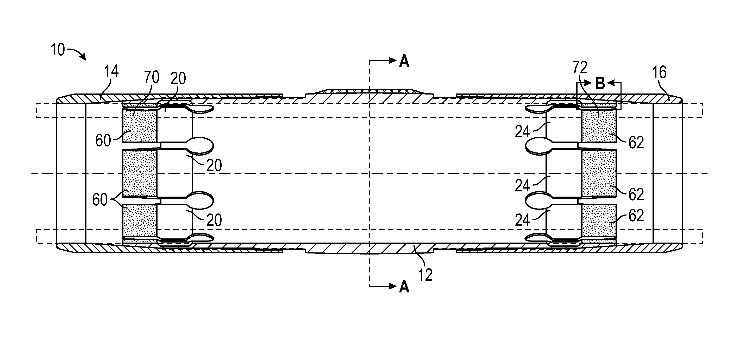
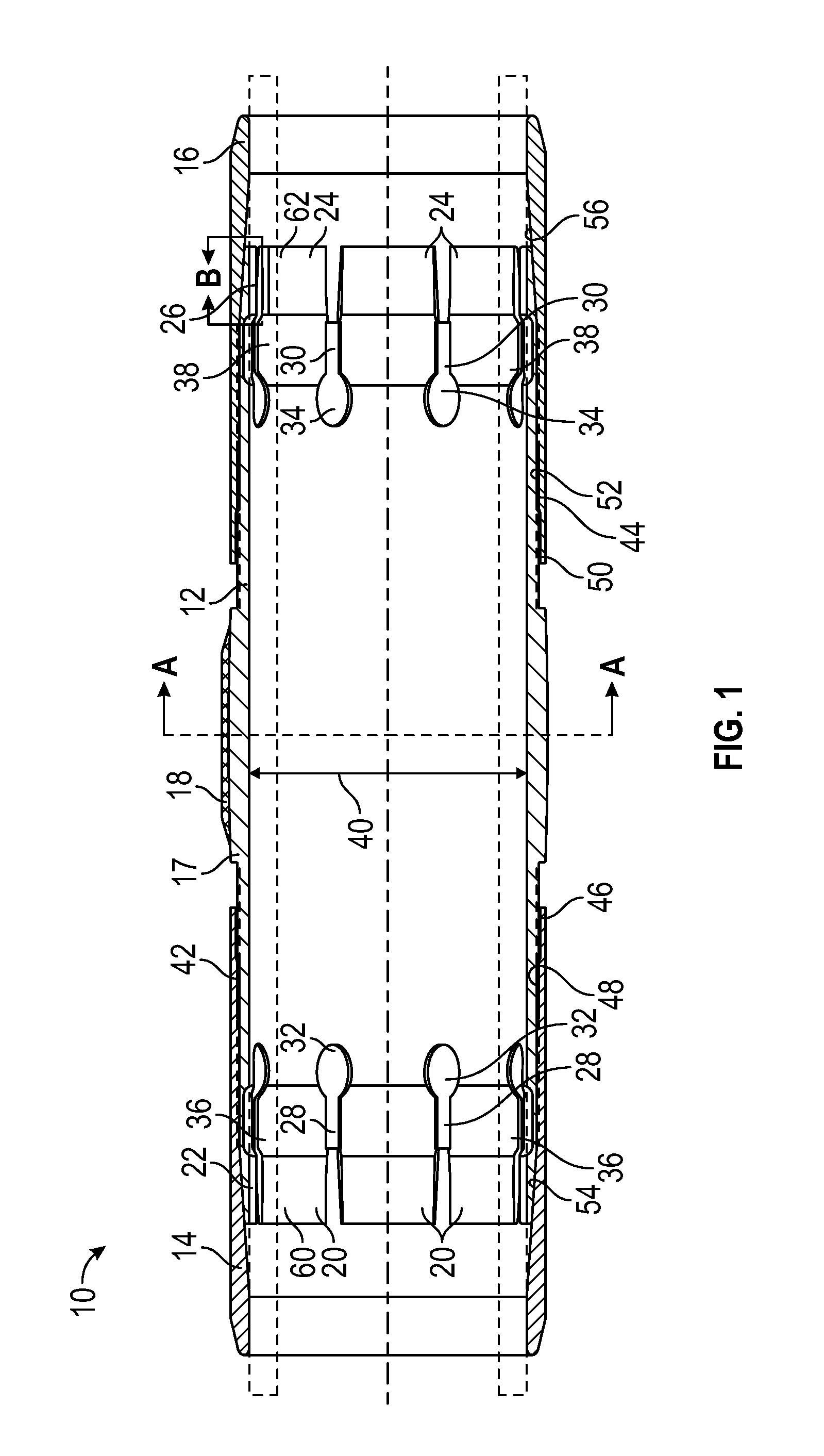
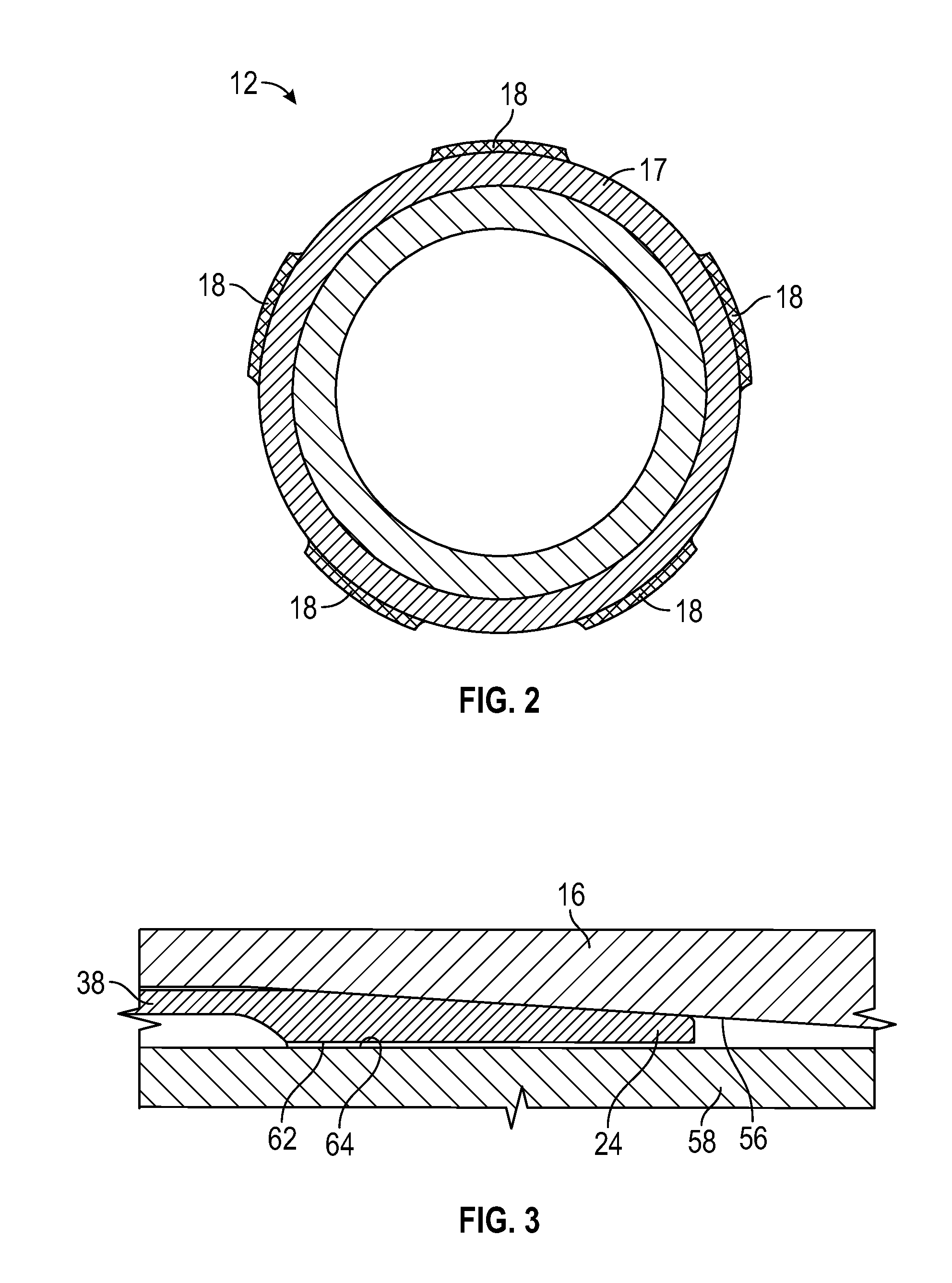
[0017]With reference to FIG. 1, stabilizer assembly 10 includes stabilizing body 12, first nut member 14, and second nut member 16. Stabilizing body 12 may be dimensioned to fit over a tubular member, such as a portion of a drill string or a drilling motor. Central portion 17 of stabilizing body 12 may include radial projection 18 extending from the outer surface of stabilizing body 12. Central portion 17 may have an increased diameter in relation to the remainder of stabilizing body 12. Radial projection 18 may be any projection extending in a radial direction beyond the outer surface of stabilizing body 12. In one embodiment, radial projection 18 may extend around the entire circumference of the outer surface of stabilizing body 12. In another embodiment, radial projection 18 may extend only partially around stabilizing body 12. As shown in FIG. 2, a set of radial projections 18 may be spaced apart around the outer surface of central portion 17 of stabilizing body 12.

[0018]Referri...


PUM


Abstract

A stabilizer assembly for a tubular member includes a stabilizing body dimensioned to fit around the tubular member, a central portion having a radial projection, and a first end having a first threaded outer surface and a set of integral first elastic members. A first nut member includes a proximal end with a threaded inner surface configured to engage the first threaded outer surface of the stabilizing body and a central portion with a first tapered inner surface configured to engage the first elastic members of the stabilizing body. Threading the first nut member onto the first end of the stabilizing body forces the first elastic members to engage the first tapered inner surface of the first nut member thereby radially flexing the first elastic members to engage the tubular member. An inner surface of a distal end of each first elastic member may include a grip section.

Description

BACKGROUND OF THE INVENTION[0001]In the drilling of oil and gas wells, downhole drilling motors may be connected to a drill string to rotate and steer a drill bit. Conventional drilling motors typically include a power assembly, a transmission assembly, and a bearing assembly. Rotation is provided by the power assembly. The transmission assembly transmits torque and speed from the power assembly to a drill bit disposed at a lower end of the drilling motor. The bearing assembly takes up the axial and radial loads imparted on the drill string during drilling.[0002]A releasable drilling stabilizer may be attached to a portion of a drill string or a drilling motor in order to stabilize the drill string or drilling motor within the wellbore. The releasable drilling stabilizer prevents unintentional key seating and reduces vibrations. Conventional releasable stabilizers include a central stiff stabilizing member having projections configured to engage an inner surface of the wellbore; sli...

Claims


Application Information

Patent Timeline
Patent Type & Authority Applications(United States)
IPC IPC(8): E21B17/10E21B19/00
CPCE21B19/00E21B17/1078E21B33/1291
Inventor VON GYNZ-REKOWSKI, GUNTHER HHRUDY, KEVIN J.WILLIAMS, MIKE V.
Owner ASHMIN HLDG LLC
Why Eureka
Try Eureka