Vehicle control device

a technology of vehicle control and control device, which is applied in the direction of propulsion parts, external condition input parameters, transportation and packaging, etc., can solve the problems of insufficient braking force, ineffective use of rotational energy of wheels, and limited braking force that can be generated by electric power regeneration, etc., to achieve the effect of increasing braking force and reducing braking for

Active Publication Date: 2017-01-19
TOYOTA JIDOSHA KK
View PDF3 Cites 18 Cited by
  • Summary
  • Abstract
  • Description
  • Claims
  • Application Information

AI Technical Summary

Benefits of technology

[0031]The antilock control of suppressing the braking lock of the wheel acts to decrease the braking force applied to the wheels. However, when the antilock control and the regeneration enhancement control are simultaneously carried out, the increase in the braking force by the regeneration enhancement control may prevent the antilock control from being appropriately carried out. In the one aspect of the present invention, the vehicle stability control means configured to carry out the antilock control of suppressing the braking lock of the wheel is provided. The prioritization means is configured to prioritize the antilock control over the regeneration enhancement control so that the antilock control and the regeneration enhancement control are not simultaneously carried out. As a result, the antilock control can be appropriately carried out without the influence of the regeneration enhancement control.

Problems solved by technology

There is an upper limit for a charge current that can be supplied to a battery, and hence, on the vehicle including the regenerative generator, a braking force that can be generated by the electric power regeneration is also limited.
Upon an emergency braking operation, a required braking force temporarily exceeds the braking force that can be generated by the electric power regeneration, and hence an insufficient amount in the braking force is compensated by a hydraulic friction braking.
Thus, a rotational energy of the wheels cannot be used effectively.
Thus, the emergency braking operation by the driver can be suppressed, and the power can thus be efficiently recovered to the battery, resulting in an increase in fuel consumption performance.
When the regeneration enhancement control and the vehicle stability control are simultaneously carried out in this way, the regeneration enhancement control may interfere with the vehicle stability control, and the vehicle stability control may not thus be carried out appropriately.

Method used


Image

  • Vehicle control device
  • Vehicle control device
  • Vehicle control device

Examples


Embodiment Construction

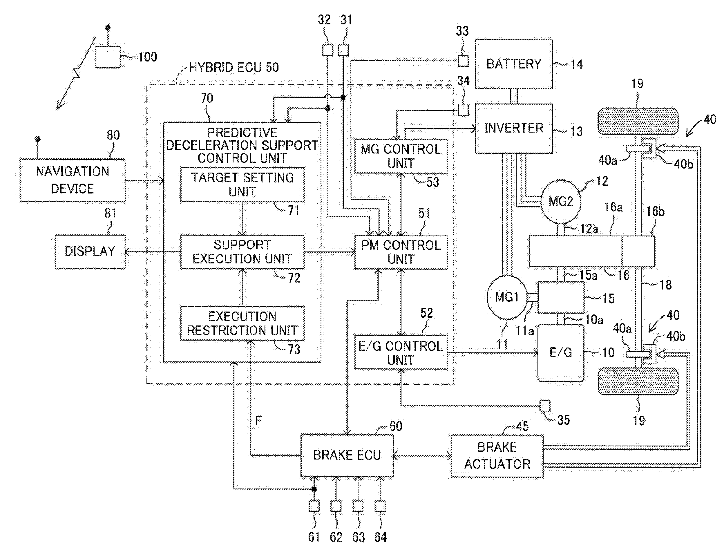
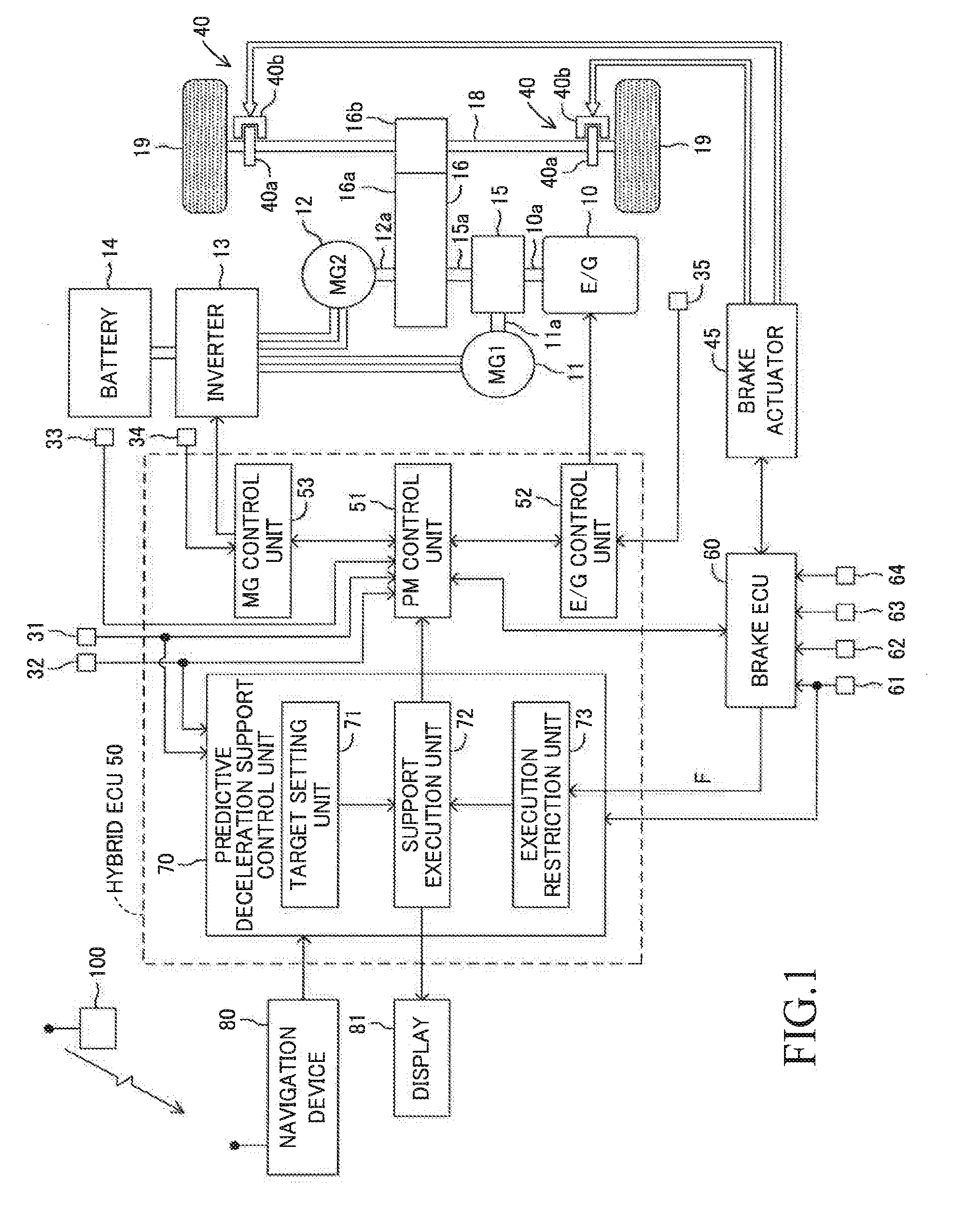
[0046]Referring to the accompanying drawings, an embodiment of the present invention is described in detail below. FIG. 1 is a schematic system configuration diagram for illustrating a vehicle control device according to an embodiment of the present invention.

[0047]A vehicle on which the vehicle control device according to this embodiment is installed is a hybrid vehicle. This vehicle includes an engine 10, a first motor generator 11 (referred to as first MG 11), a second motor generator 12 (referred to as second MG 12), an inverter 13, a battery 14, a power distribution mechanism 15, a driving force transmission mechanism 16, and a hybrid electronic control unit 50 (referred to as hybrid ECU 50) as a travel drive device.

[0048]The engine 10 is a gasoline engine or a diesel engine.

[0049]The power distribution mechanism 15 is configured to distribute a driving force of the engine 10 to power for driving an output shaft 15a of the power distribution mechanism 15 and power for driving t...


PUM


Abstract

Appropriate vehicle stability control is enabled in a vehicle configured to carry out regeneration enhancement control. A predictive deceleration support control unit is configured to set a position at which the vehicle is predicted to finish deceleration as a target deceleration end position, and guide a driver to release an accelerator pedal so that the deceleration of the vehicle is finished at the target deceleration end position, to thereby carry out regeneration enhancement control under a state in which the accelerator pedal is released so as to generate a larger deceleration than in a normal state. The predictive deceleration support control unit is configured to read a vehicle stability control flag from a brake ECU and stop the regeneration enhancement control when the vehicle stability control is being carried out.

Description

BACKGROUND OF THE INVENTION[0001]1. Field of the Invention[0002]The present invention relates to a vehicle control device, which is configured to support an operation of a driver so as to increase an electric power regeneration amount in a vehicle capable of generating a braking force by recovering electric power to an in-vehicle battery.[0003]2. Description of the Related Art[0004]For example, as proposed in International Patent WO2012 / 053106A1, there is known a drive support device, which is configured to set a target stop position for a vehicle and to issue an instruction to release an accelerator pedal so that the vehicle stops at the target stop position. Moreover, as proposed in Japanese Patent Application Laid-open No. 2015-19521, there is known a vehicle including a regenerative generator, which is configured to set such a deceleration start position as to increase an electric power regeneration amount to be recovered to a battery during deceleration travel up to a target st...

Claims


Application Information

Patent Timeline
Patent Type & Authority Applications(United States)
IPC IPC(8): B60W30/182B60W30/18B60W10/08B60K6/40B60W50/14B60W30/045B60K6/445B60W10/188B60W20/14
CPCB60W30/182Y10S903/951B60W30/18127B60W10/08B60W30/18172B60W20/14B60W50/14B60W30/045B60K6/445B60K6/40B60W2540/10B60W2720/26B60Y2200/92B60Y2300/022B60Y2300/18125B60Y2300/18175B60Y2300/182Y10S903/93B60W10/188B60W10/06B60W10/18B60W30/02B60W30/18109B60W2520/10B60W2520/28B60W2540/12B60W2540/14B60W2540/18B60W2556/50B60W2710/182B60W2720/106B60W10/184B60W20/12B60W2050/0091B60W2050/0094Y02T10/62
Inventor OGURI, HARUKIKOGANEMARU, SATOSHIMATSUNAGA, NAOYA
Owner TOYOTA JIDOSHA KK
Why Eureka
Try Eureka