Well barrier method and apparatus

Active Publication Date: 2017-01-19
SCHLUMBERGER TECH CORP
View PDF6 Cites 2 Cited by
  • Summary
  • Abstract
  • Description
  • Claims
  • Application Information

AI Technical Summary

Benefits of technology

[0046]The displacement barrier may extend between the running string and engage a wall of the wellbore. Such an arrangement may provide a degree of isolation between the settable medium being injected and other resident wellbore fluids. This may minimise contamination of the settable medium,

Problems solved by technology

Also, there may be occasions where long term suspension of a well is required, for example where reserves are located but production is not yet economically viable.

Method used


Image

  • Well barrier method and apparatus
  • Well barrier method and apparatus
  • Well barrier method and apparatus

Examples


Example

DETAILED DESCRIPTION OF THE DRAWINGS

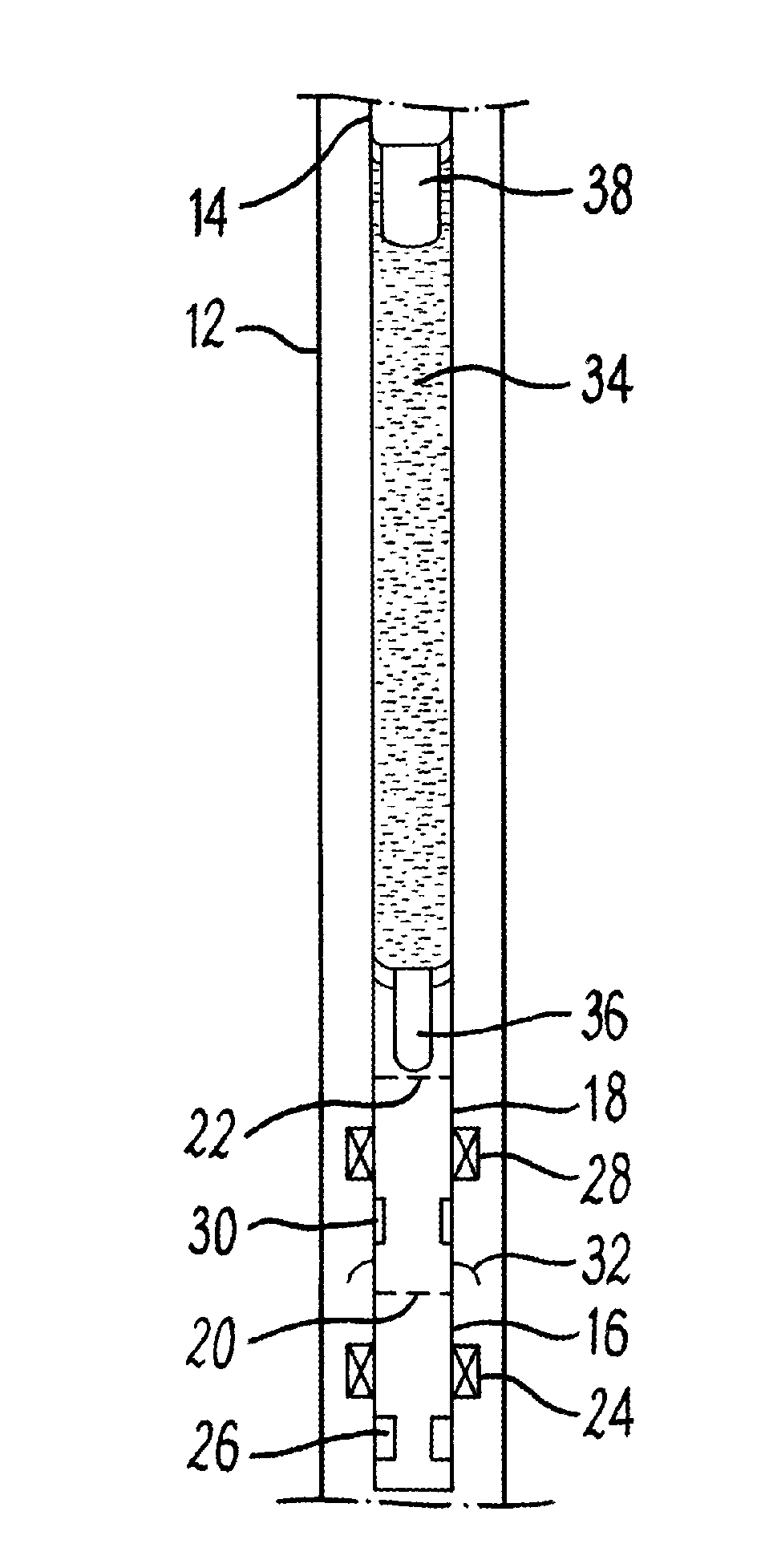
[0121]Aspects of the present invention relate to a method and apparatus for creating a barrier in a wellbore. There are multiple situations where such a barrier may be required or is advantageous. However, for the purposes of the present exemplary description, an example apparatus will be described for use in setting a barrier in a wellbore during well abandonment.

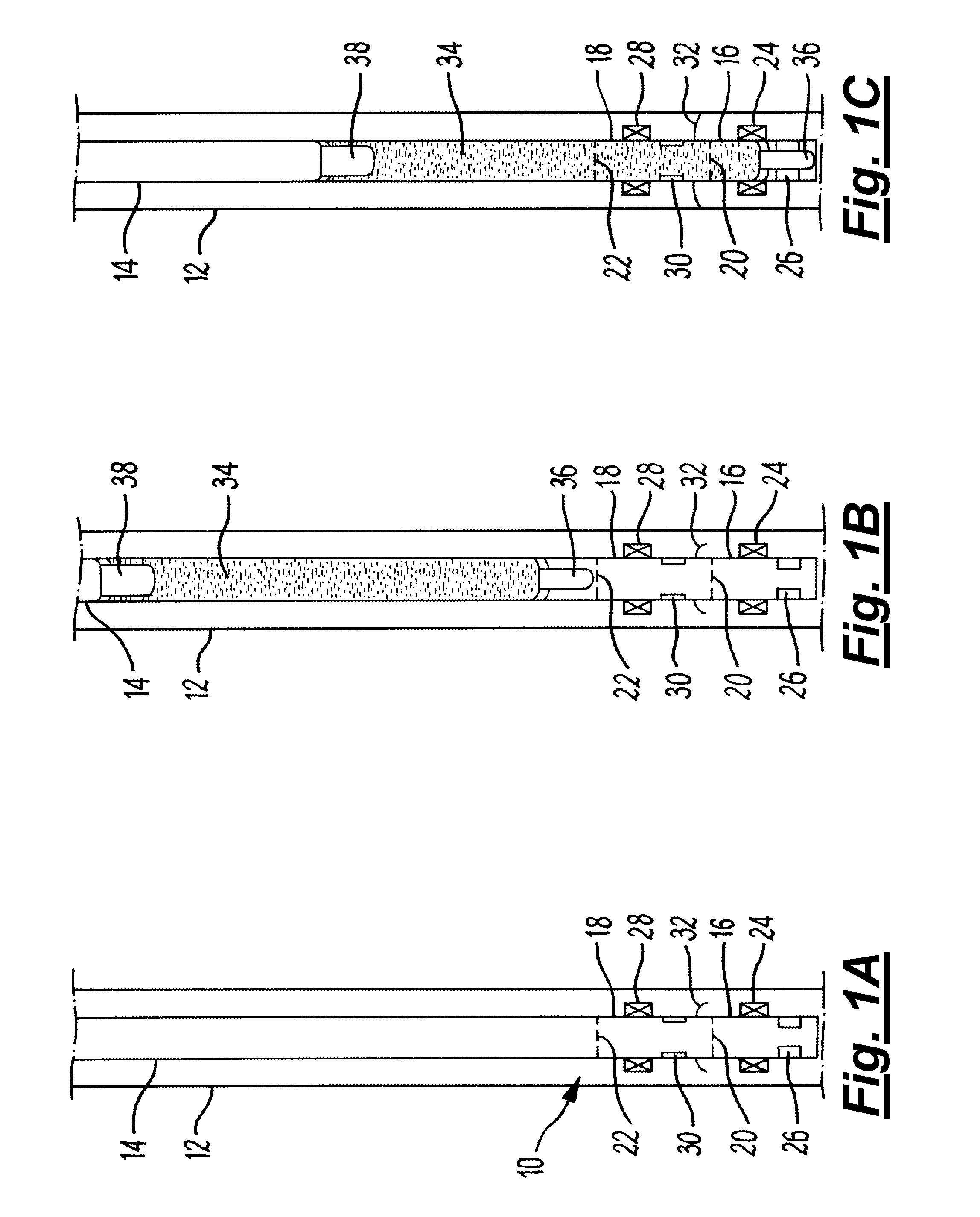
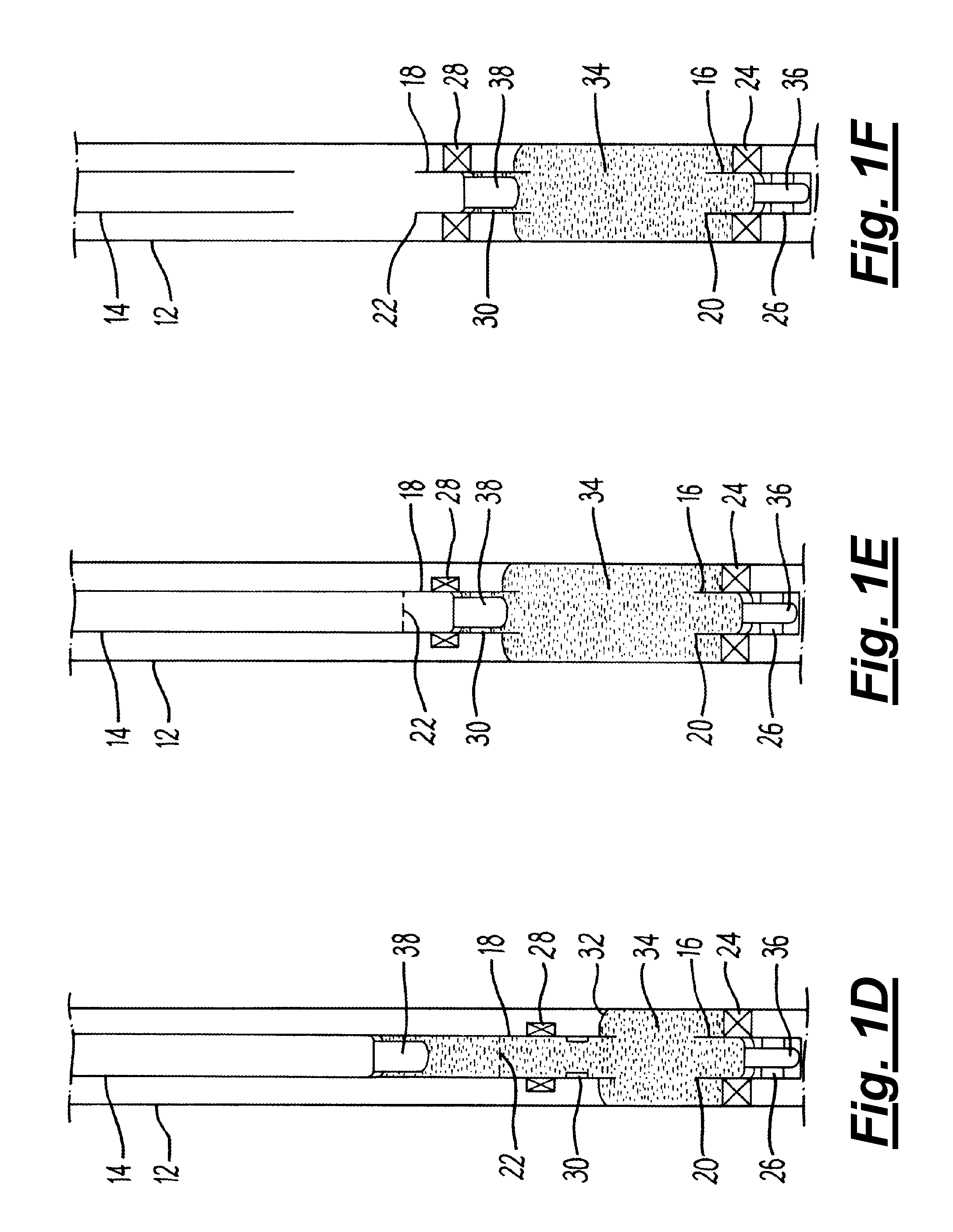
[0122]FIGS. 1A to 1F diagrammatically illustrate sequences of a method of setting a barrier in a wellbore utilising an apparatus 10 according to an exemplary embodiment of the present invention. In the present embodiment the wellbore includes a string of tubing 12, such as casing, although it should be recognised that in other embodiments the wellbore may be defined by or comprise an open hole section.

[0123]Referring initially to FIG. 1A, the apparatus 10 includes a running string 14 which supports at one end thereof first and second plug assemblies 16, 18. The running string includes a ...


PUM


Abstract

A method for setting a barrier within a wellbore comprises deploying a first plug assembly (16) into a wellbore on a running string, wherein the first plug assembly comprises an extendable arrangement (24), and then setting the first plug assembly within the wellbore by extending the extendable arrangement. A settable medium is injected via the running string into the wellbore above the first plug assembly. To be accompanied, when published, with FIG. 1F

Description

FIELD OF THE INVENTION[0001]The present invention relates to a method and apparatus for establishing a plug or barrier within a well, for example for use in well abandonment.BACKGROUND TO THE INVENTION[0002]In the oil and gas exploration and production industry there are many reasons for abandoning a well, including end-of-life decommissioning, isolating an exploration well and the like. Also, there may be occasions where long term suspension of a well is required, for example where reserves are located but production is not yet economically viable. Any wellbore decommissioning or abandoning (temporary or permanent) must follow legislation appropriate for the region in question. Such legislation typically calls for a robust barrier or plug to be set within the wellbore. In many cases a cement plug is often used, providing a barrier of low permeability, long term integrity and low levels of shrinking. Also, such legislation typically requires multiple barriers to be established, to p...

Claims


Application Information

Patent Timeline
IPC IPC(8): E21B33/138E21B33/12
CPCE21B33/138E21B33/12E21B36/00E21B33/128E21B33/16E21B17/07E21B17/06E21B33/1204E21B33/13E21B33/126E21B33/1285E21B33/1292E21B33/1293E21B33/134
Inventor MOYES, PETER
Owner SCHLUMBERGER TECH CORP
Why Eureka
Try Eureka