Cannula insertion device

a technology of cannula and insertion device, which is applied in the direction of trocar, other medical devices, infusion needles, etc., can solve the problems of needle stick injury, prior art connection hub suffer at least, and infection risk, so as to minimize contamination and needle stick injury

Active Publication Date: 2010-08-12
INFUTECH LTD
View PDF18 Cites 21 Cited by
  • Summary
  • Abstract
  • Description
  • Claims
  • Application Information

AI Technical Summary

Benefits of technology

[0014]According to a first aspect of the present invention there is provided a cannula insertion device comprising a frame, a hub mounted to the frame and arranged to be slidably moveable from a first position to a second position in a first direction and a needle projecting in the first direction from the hub and carrying a detachable assembly including a cannula, the needle being shielded by the frame when the hub is in the first position, the frame and hub arranged to allow the hub to be moved from the first position to the second position in the first direction so as to insert the cannula into a patient and to be moved in a second, reverse direction to a third position in which the frame shields the needle. Thus, the needle is shielded before and after it is inserted which can help to minimise possible contamination and needle stick injury.

Problems solved by technology

Existing insertion devices suffer the drawback that the needle is often exposed before and / or after insertion, thereby allowing possible contamination of the needle and exposing the operator to so-called “needle stick” injury, which carries with it a risk of infection.
However, the prior art connecting hub suffers at least two drawbacks.
Firstly, the hollow needle on the connecting hub is itself a potential hazard and could lead to needle stick injury.
Secondly, the connecting hub can be difficult to align and orientate with the cannula housing.
However, this arrangement only allows one fluid to be delivered at a time.
However, this can be inconvenient for the patient since such a device can restrict mobility.

Method used


Image

  • Cannula insertion device
  • Cannula insertion device
  • Cannula insertion device

Examples


Embodiment Construction

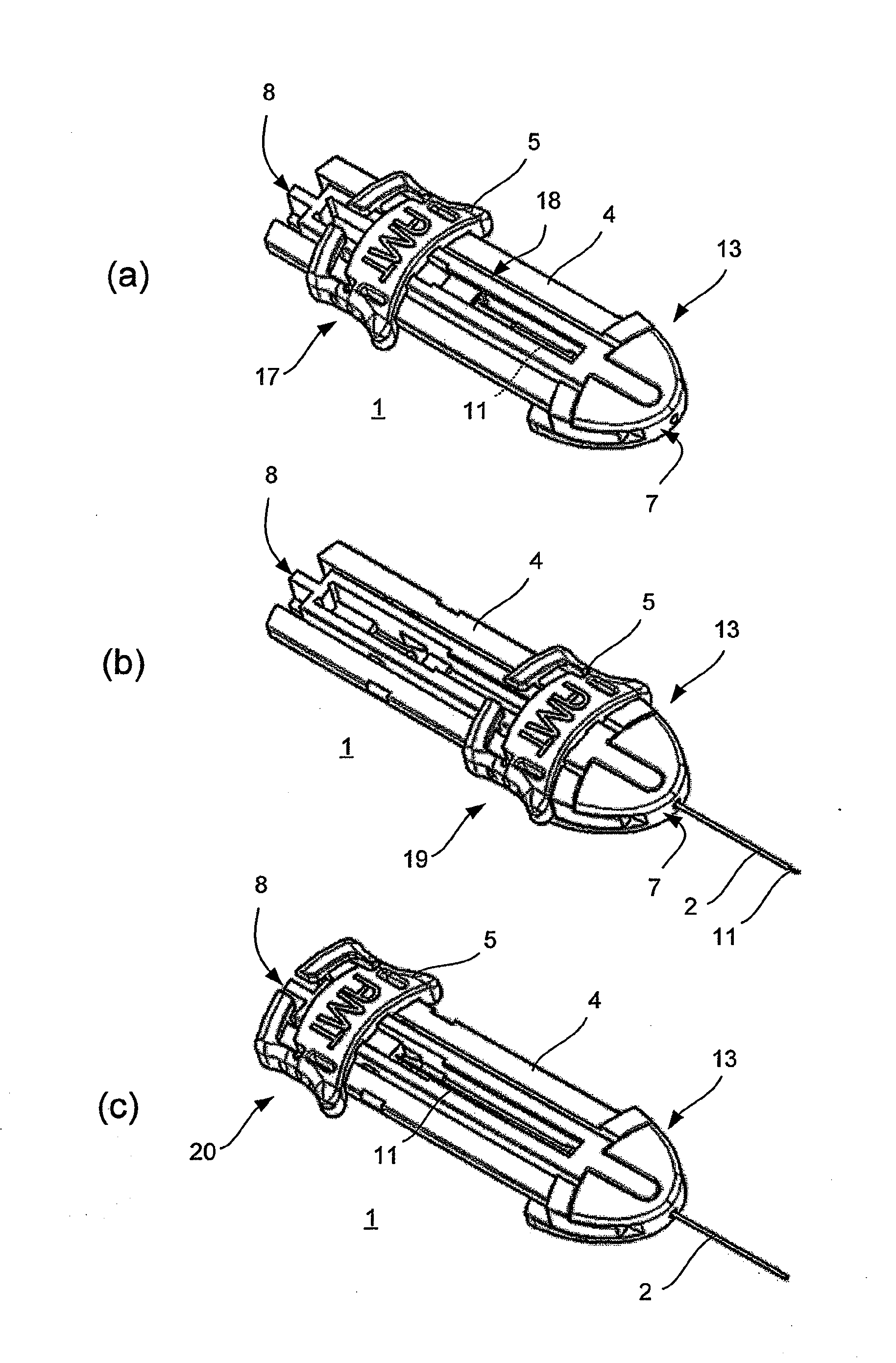
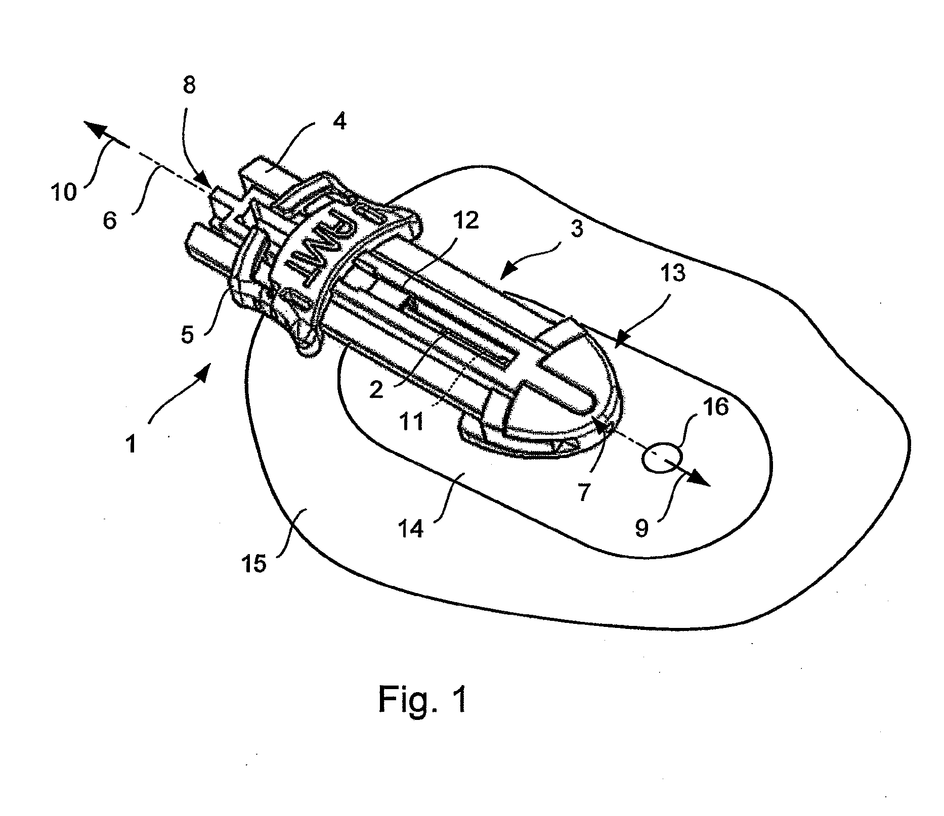
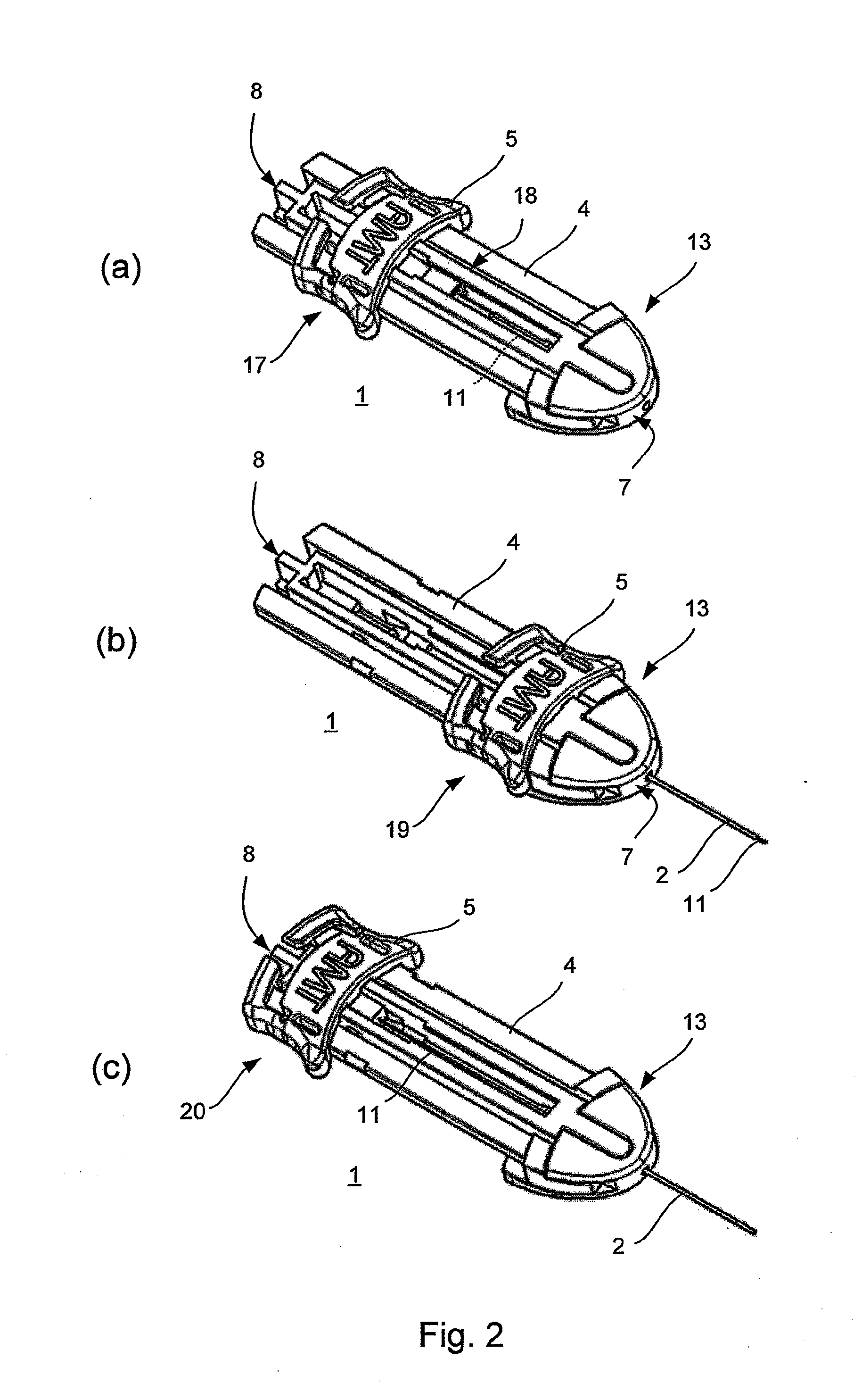
[0070]Referring to FIG. 1, an assembly 1 for inserting a soft cannula 2 or “catheter” into a patient and, once inserted, holding it in place in accordance with the present invention is shown. The assembly 1 includes a device 3 for inserting the cannula (hereinafter referred to as the “insertion device”) having an elongate frame 4 (hereinafter referred to as the “chassis”) and a hub 5 slidably moveable along the chassis 4. The hub 5 is hereinafter referred to as the “slider”.

[0071]The slider 5 travels along a longitudinal axis 6 running between first and second ends 7, 8 of the chassis 4 in first and second directions 9, 10. During normal use, the first and second directions 9, 10 are usually forwards (towards the patient's skin) and backwards respectively and so these terms will be used hereinafter.

[0072]A needle 11 projects forwardly from the slider 5 and carries, on its shaft 11b (FIG. 10), a detachable sub-assembly 12 (hereinafter referred to as the “septum assembly”) which inclu...


PUM


Abstract

A cannula insertion device comprises an elongate frame (4) and a hub (5) mounted to the frame and arranged to be slidably moveable from a first position forwards along a longitudinal axis to a second position relative to the frame and a needle (11) projecting forwards from the hub and carrying a detachable cannula (2) assembly including a cannula. The frame and hub are arranged to allow the hub to be moved forwards from the first position to the second position so as to insert the cannula into a patient and to be drawn backwards to a withdrawn position. The needle is shielded by the frame when the hub is in the first position and also when in the withdrawn position.

Description

FIELD OF THE INVENTION[0001]The present invention relates to a cannula insertion device.[0002]The present invention also relates to a connector for connecting a tube to an infusion device.BACKGROUND[0003]Treatment of some medical conditions involves administering a drug (or a combination of drugs) subcutaneously or intravenously into a patient.[0004]A drug delivery system can be divided in two parts, namely a device for supplying the drug (such as a bag, pump or syringe) and a tubing arrangement for delivering the drug into the patient.[0005]The tubing arrangement includes a soft cannula, which can also be referred to as a catheter. One end of the cannula is inserted into the patient, leaving the other end available for connection to the drug-supplying device. The cannula is held in place by taping the cannula to the surface of the skin of the patient or by using a housing which itself is attached to the surface of the skin.[0006]To insert the cannula into the patient, a device is u...

Claims


Application Information

Patent Timeline
Patent Type & Authority Applications(United States)
IPC IPC(8): A61B17/34
CPCA61M5/1408A61M5/158A61M5/3271A61M25/0113A61M2005/3247A61M25/0631A61M2005/1585A61M2005/1587A61M25/0606A61B17/3421A61M39/10A61M39/1011A61M2005/1583
Inventor MORRISSEY, RAYMCLELLAN, STEVENLILLIS, BARRY
Owner INFUTECH LTD
Why Eureka
Try Eureka