
Wall plate system

Active Publication Date: 2017-01-26
ABL IP HLDG
View PDF7 Cites 32 Cited by
  • Summary
  • Abstract
  • Description
  • Claims
  • Application Information

AI Technical Summary

Problems solved by technology

However, a pry tool is still required for their removal.
The required tool is an inconvenience to the user, and the p

Method used


Image

  • Wall plate system
  • Wall plate system
  • Wall plate system

Examples


Example

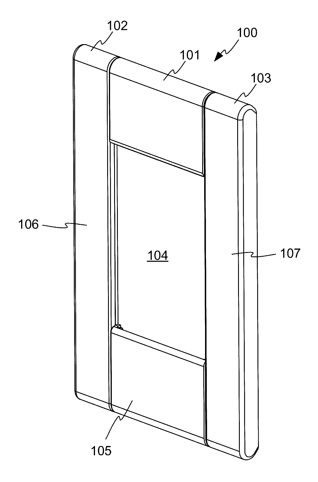
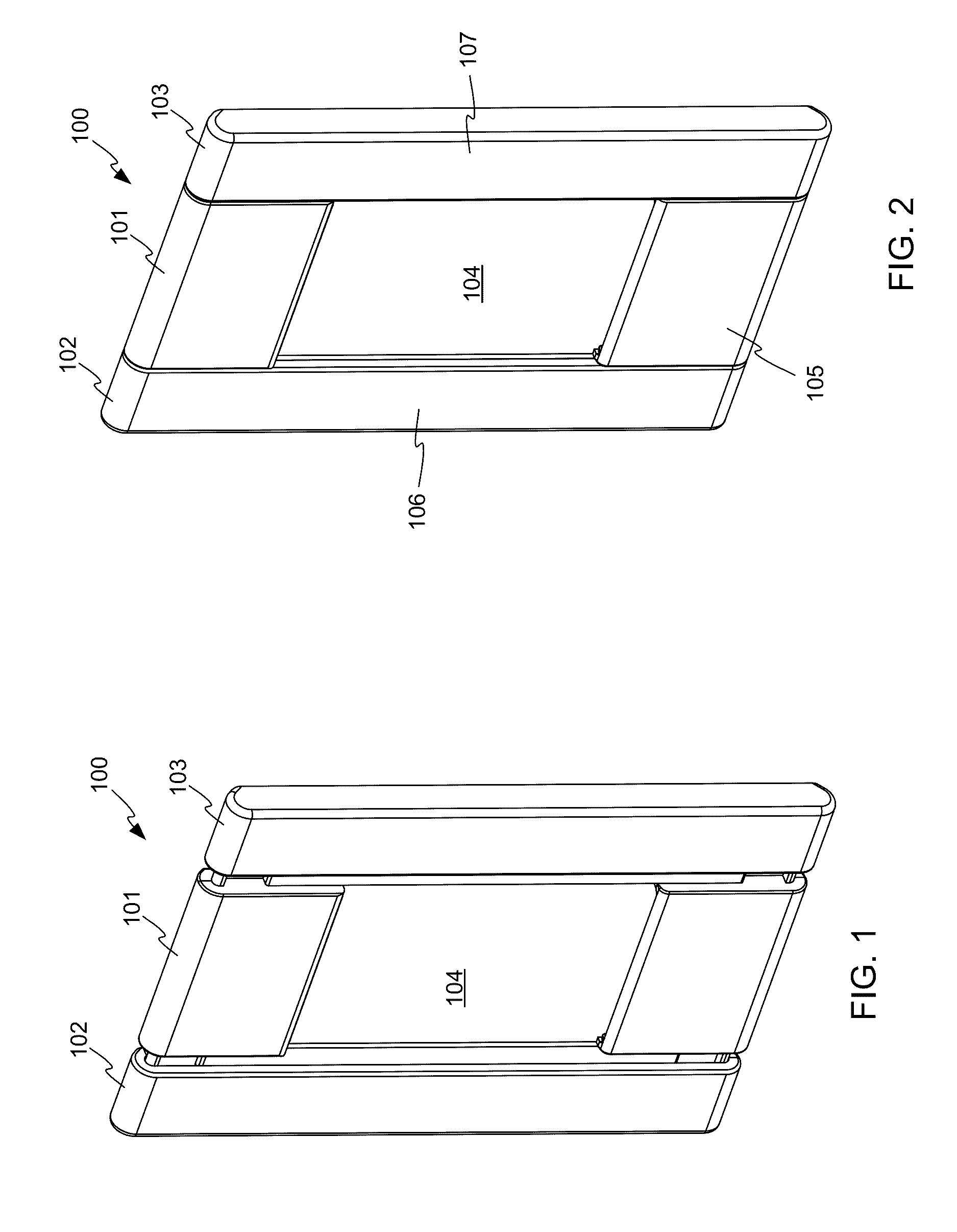
[0004]FIG. 1 is a front perspective view of a wall plate in accordance with embodiments of the invention, in an open position.

[0005]FIG. 2 is a front perspective view of the wall plate of FIG. 1, in a closed position.

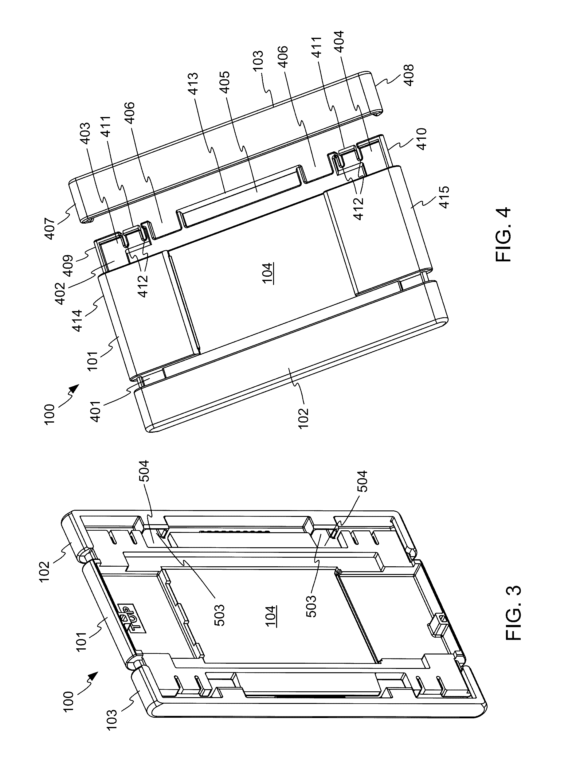
[0006]FIG. 3 is a rear perspective view of the wall plate of FIG. 1, in an open position.

[0007]FIG. 4 is a front perspective view of the wall plate of FIG. 1, partially disassembled.

[0008]FIG. 5 is a rear perspective view of the wall plate of FIG. 1, partially disassembled.

[0009]FIG. 6 is a perspective view of a mounting plate, in accordance with embodiments of the invention.

[0010]FIG. 7 is a rear perspective view of the wall plate of FIG. 1 in position to mount to the mounting plate of FIG. 6.

[0011]FIG. 8 is a rear perspective view of the wall plate of FIG. 1 mounted to the mounting plate of FIG. 6.

[0012]FIG. 9 is a front perspective view of the wall plate of FIG. 1, installed on a wall.

[0013]FIG. 10 is a front exploded perspective view of a wall plate system including...


PUM


Abstract

A wall plate and system for covering an electrical component in an electrical box. The wall plate includes a base plate having a central aperture, and two trim pieces that join at the sides of the base plate to complete the wall plate. The base plate may include two side edges and wing portions extending from the side edges, and the trim pieces slide onto the respective side wing portions. The trim pieces may have features to engage a mounting plate attached to the electrical box or the electrical component, to capture the wall plate over the electrical box. A locking mechanism may be provided to lock the trim pieces in their inward positions against the base plate. The wall plate may be attachable without the use of tools or fasteners.

Description

[0001]This application claims the benefit of U.S. Provisional Patent Application No. 62 / 194,483 filed Jul. 20, 2015 and titled “Wall Plate System”, the entire disclosure of which is hereby incorporated by reference herein for all purposes.BACKGROUND OF THE INVENTION[0002]Wall plates are positioned on a wall over light switches, outlets, controls, etc. to impart a polished appearance to the installation. A wall plate is typically mounted onto and over an exposed mounting plate connected to an electrical box in the wall. Wall plates have historically been mounted onto the mounting plates with screws or other mechanical fasteners, thus requiring tools both for their installation and removal / replacement. Wall plates have been designed that eliminate the need for unsightly mechanical fasteners. Rather, such plates snap-fit onto a mounting plate to secure the wall plate to the wall. However, a pry tool is still required for their removal. The required tool is an inconvenience to the user,...

Claims


Application Information

Patent Timeline
IPC IPC(8): H02G3/08H02G3/14H02G3/10
CPCH02G3/083H02G3/14H02G3/10
Inventor JOHNSON, JOHN RICHARDOKOLI, CHUKWUNONSO NZUBECHUKWUHICKOK, JOHN T.WESTRICK, JR., RICHARD LEE
Owner ABL IP HLDG
Learn More