Building construction for forming columns and beams within a wall mold

a building construction and mold technology, applied in the direction of walls, girders, heat-insulating materials, etc., can solve the problems of inability to install concrete columns or beams, inability to use structural insulated panels with foam core and plywood exterior, and inability to adapt to the needs of construction. to achieve the effect of easy fixing into a concrete structur

Inactive Publication Date: 2009-04-30
LEBLANG DENNIS WILLIAM
View PDF91 Cites 90 Cited by
  • Summary
  • Abstract
  • Description
  • Claims
  • Application Information

AI Technical Summary

Benefits of technology

[0108]Another aspect of the pending patent is the formation of an insulated flange on a wall forming structure. The insulated flange can be used as an independent framing member or can be installed within a concrete column or continuous concrete wall. The insulated flange allows concrete to flow around the insulated flange allowing future penetrations into a concrete wall like screws or nails to easily be fastened into a concrete structure. In addition, a scaffolding connector could easily be attached to the interior forming structure as well as removing the scaffolding support connector as well as installing and removing any temporary bracing after the concrete is installed within the molds.

Problems solved by technology

Insulated concrete forms have been used in construction; however some types of ICF (Insulated Concrete Forms) are not capable of installing concrete columns or beams within the ICF walls as they were only intended to be used as full width concrete walls and other ICF's have no flexibility in column spacing.
Structural insulated panels (SIP's) with their foam core and plywood exterior have a very limited use.
The concrete columns are only one channel wide and therefore the column size or structural capacity is very limited.
The double wall construction is expensive solution to form a concrete column and a method to support the sides of the beam on top of the wall.
Since the concrete beam is a mold, the size is also limited to change without ordering different molds for different size beams.
The ribbed foam panels limits the size, spacing and structural integrity of the concrete beams as well as the array of concrete columns.
Since the holes for the concrete are only support by foam, the size is limited as the concrete will deform as well as break the foam panels.
Again the beam pocket is also fragile as there is not support to stop the wet concrete from deforming the beam.
The panel does not appear strong enough to support the wet concrete at the columns and especially at the wall corners.
The size of the columns and beams is limited to the strength of the glue holding the panel together.
None of the Lanahan patents use their panels to form concrete columns or beams.
Since these spreaders are made of plastic, the spreaders are easily breakable especially when trying to align them with the recessed grooves above.
When connected the rigid insulation along with the plastic connector really just form another type of ICF blocks except here the scallops adds more expensive and doesn't really serve any function.
These panels would be a very expensive to fabricate as well as to install at a construction site.

Method used


Image

  • Building construction for forming columns and beams within a wall mold
  • Building construction for forming columns and beams within a wall mold
  • Building construction for forming columns and beams within a wall mold

Examples


Embodiment Construction

[0167]A building panel and method of forming a concrete column and beam using a skeleton assembly to encase a forming structure and embedded a hardenable material such as concrete within the forming structure. Various types of skeleton assembly's are formed using metal or plastic forming structures with reinforcing means, insulation and rigid boards.

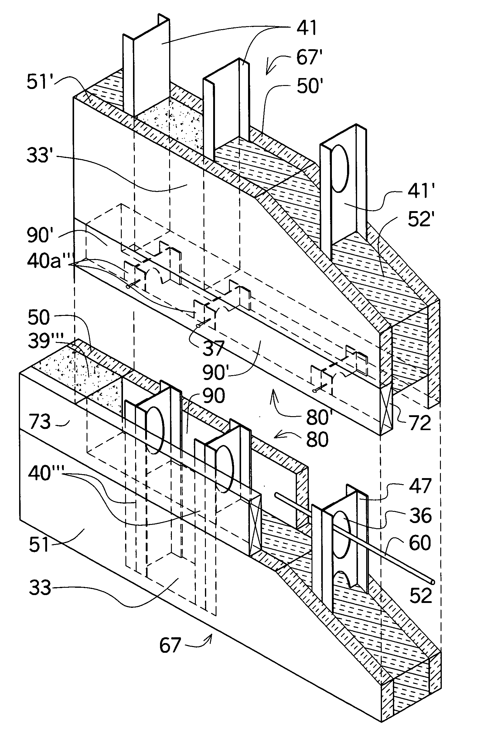
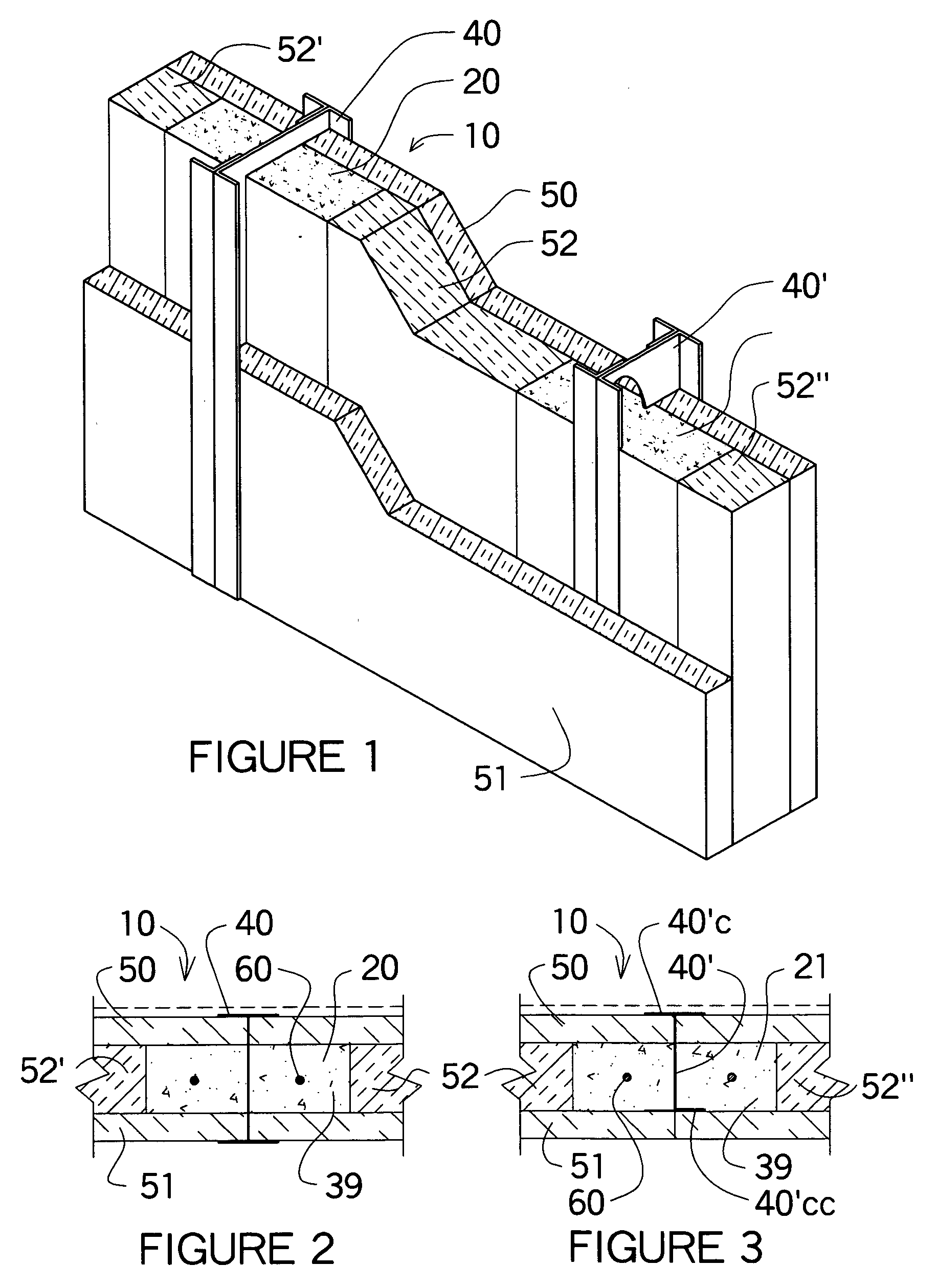
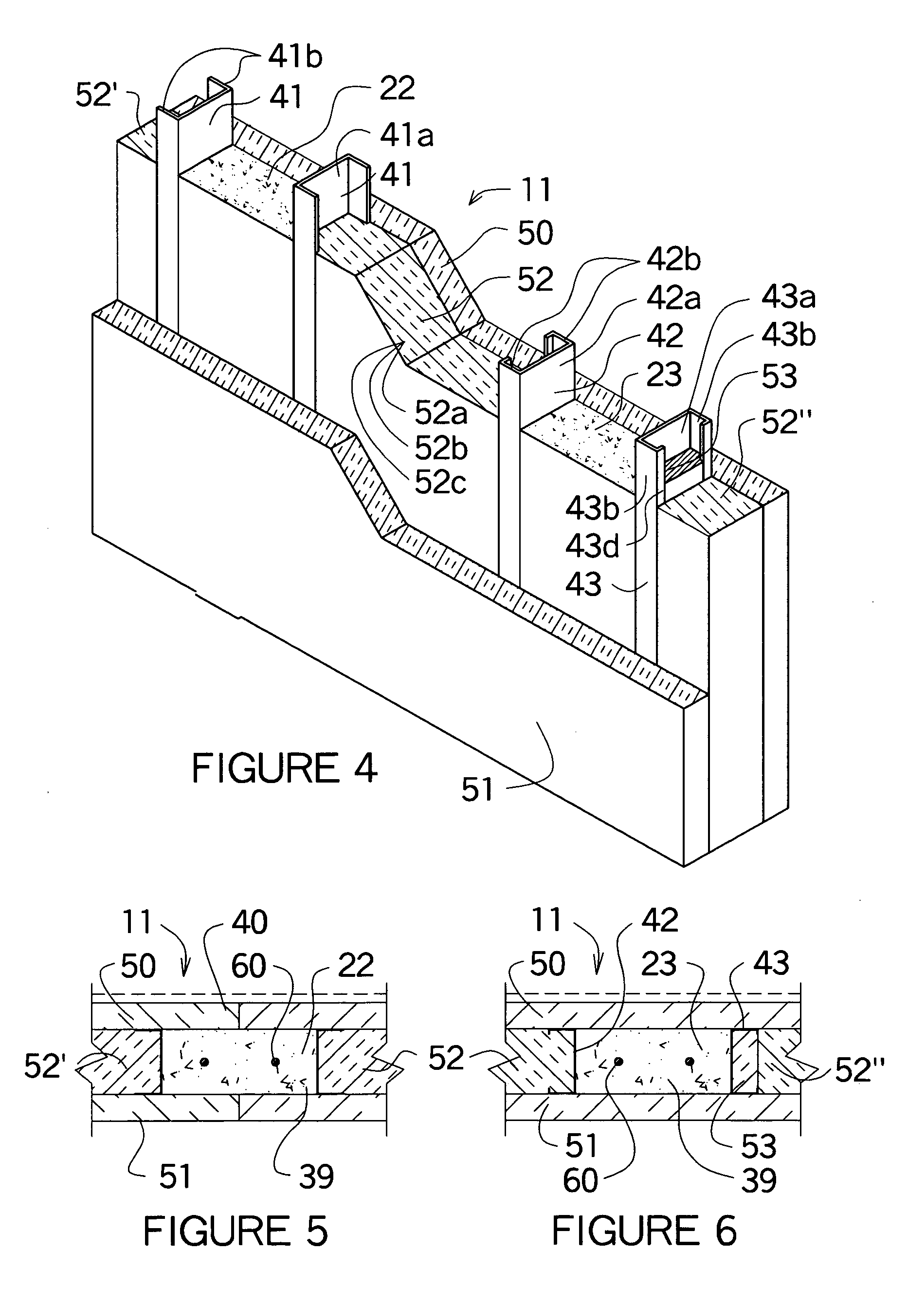
[0168]After review of the existing and pending patents, one can recognize the differences in this patent application. In FIG. 1 a wall mold 10 is shown in isometric view with two different column molds 20&21. The wall mold 10 consists of a rigid board 50 and rigid insulation 51 as the outer surfaces of the wall mold 10. The interior of the column molds 20&21 is also shown in a plan view drawing in FIG. 2 and FIG. 3. The width of the column molds 20&21 are determined by the thickness of the spacer insulation 52 located between the rigid board 50 and the rigid insulation 51. On the other hand, the distance between the spacer insulation 52′...


PUM


Abstract

The present invention relates to an improved wall system where a wall form mold has a structural insulated core assembled to form a structural insulated panel (SIP) to form a concrete beam and concrete column to be poured anywhere within the wall as well as between building modules when placed together and erected vertically. The interlocking wall molds interlock within the wall as well as between panels and modules. The wall panels allow concrete columns and beams to be formed in any size and shape. The structural insulated core consists of interlocking foam spacers and support channels which can be glued or screwed together to form an independent wall or as part of a precast wall with columns and beams integrated within the wall panels. Insulated flanges within the wall forming mold separates the wall forming structure from the wall surfaces.

Description

REFERENCE TO RELATED APPLICATIONS[0001]A provisional patent application No. 61 / 000,112 was filed on Oct. 24, 2007 by LeBlang for this patent application, plus 61 / 137,224 was filed on Jul. 29, 2008. In addition a patent pending application US 2007 / 0044392 was filed on Nov. 12, 2004 by LeBlang and another pending application US 2008 / 0062308 on Jun. 23, 2008.BACKGROUND OF THE INVENTION[0002](1) Field of the Invention[0003]The present invention relates to an improved wall system where a wall form mold has a structural insulated core assembled to form a structural insulated panel (SIP) to form a concrete beam and concrete column to be poured within the wall. In addition, the wall forming structure of the wall mold penetrates into the foundation and into the wall form mold above allowing the concrete column and beam to penetrate into the adjacent form molds. The wall molds can be used to form modular buildings units and can be used to create larger columns and beams when two modular build...

Claims


Application Information

Patent Timeline
Patent Type & Authority Applications(United States)
IPC IPC(8): E04B1/18
CPCE04B1/165E04B1/80E04B2/7412E04C2003/0473E04B2/8647E04C3/09E04B2/8635
Inventor LEBLANG, DENNIS WILLIAM
Owner LEBLANG DENNIS WILLIAM
Why Eureka
Try Eureka