Local phase correction

a phase correction and local technology, applied in the field of integrated circuits and methods thereof, can solve the problems of low phase correction accuracy, and high cost, and achieve the effects of reducing phase errors that are typically associated with length mismatch, reducing signal degradation in coupled line bends, and facilitating implementation

Active Publication Date: 2017-01-26
MARVELL ASIA PTE LTD
View PDF1 Cites 0 Cited by
  • Summary
  • Abstract
  • Description
  • Claims
  • Application Information

AI Technical Summary

Benefits of technology

[0011]It is to be appreciated that embodiments of the present invention provide many advantages over conventional techniques. Among other things, by matching the length of communication lines at bend regions, phase errors that are typically associated with length mismatch is greatly reduced, with minimal introduction of mode conversion. Through reduction of phase errors, signal degradation in coupled line bends is minimized and / or eliminated, as demonstrated by actual performance measurements explained below. In addition, embodiments of the present invention are compatible with existing systems and methods thereof, and thus can be easily implemented. There are other benefits as well.

Problems solved by technology

One of the challenges has been to fit a large number of components into IC packages and for these components to communicate with one another at high speed.
However, as described below, they have been inadequate.

Method used


Image

  • Local phase correction
  • Local phase correction
  • Local phase correction

Examples


Embodiment Construction

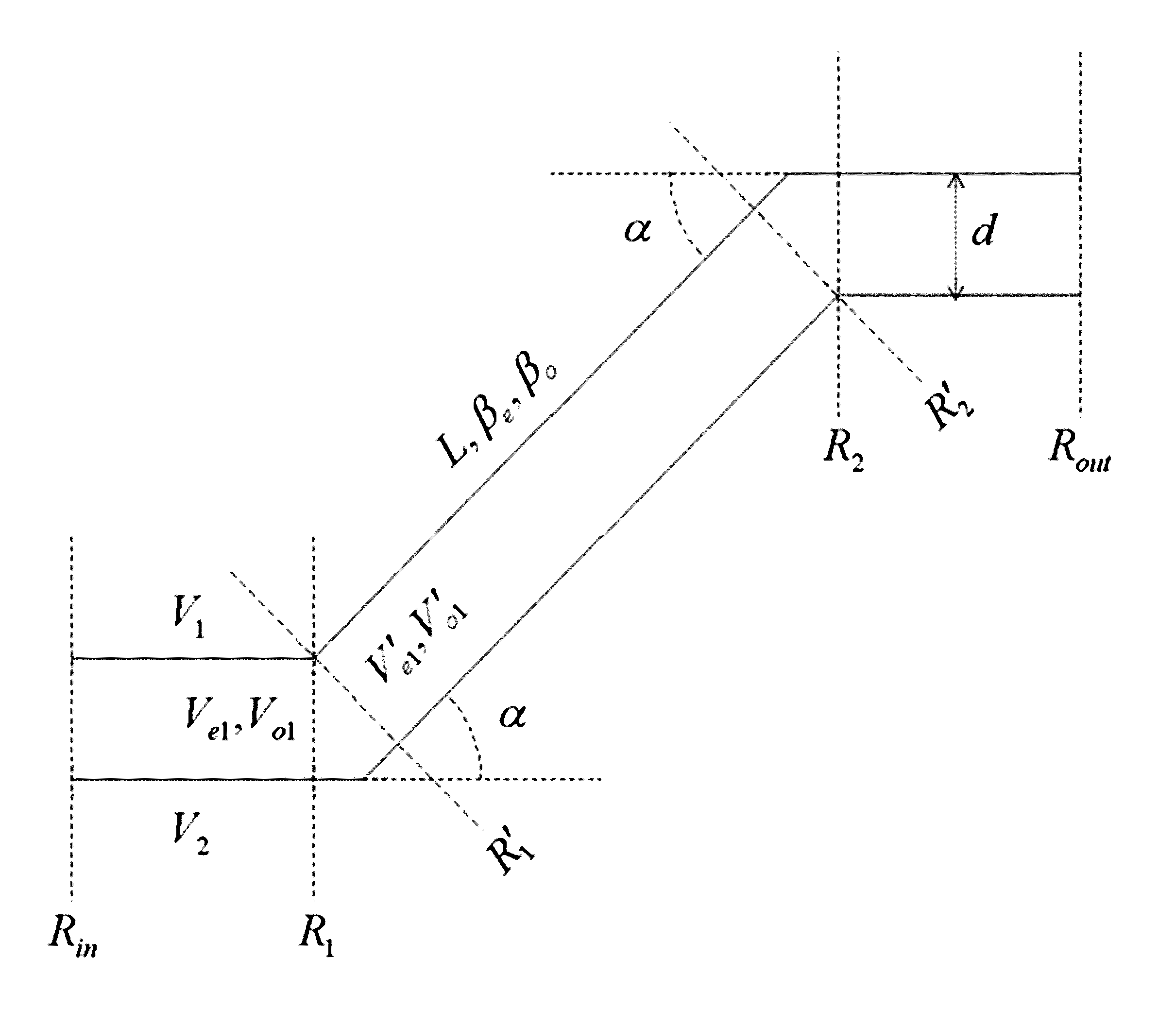
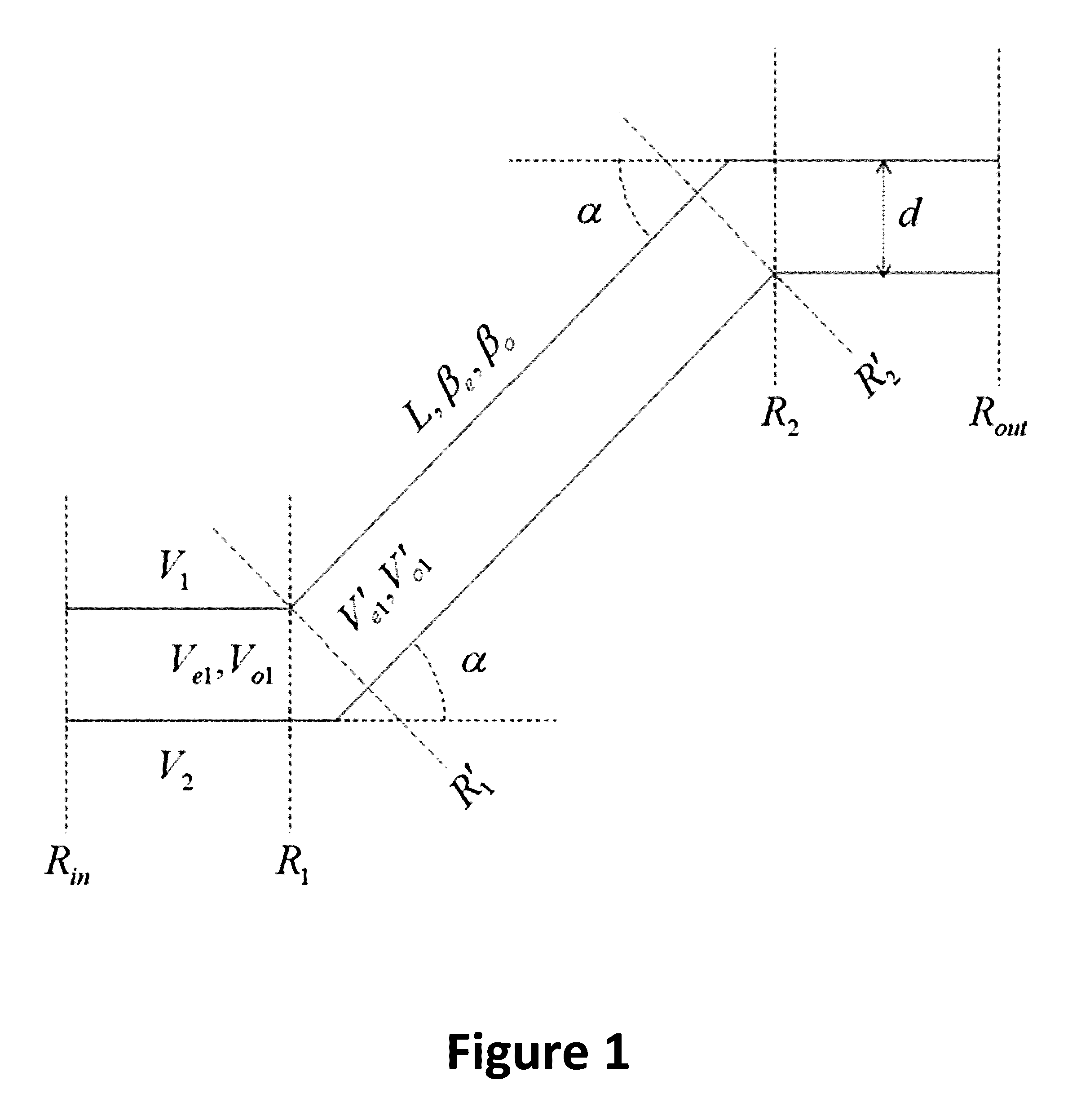
[0021]The present invention is directed to integrated circuits and methods thereof. More specifically, embodiments of the present invention provide a local correction for bending communication line pairs. In an IC package, a pair of communication lines is used to provide a physical link for data communication between two or more components. At regions where the pair of communication lines is bent, the inner bend line is extended in length and shaped to match the length of the outer bend line while preserving integrity of its signal propagation characteristics, thereby providing local phase correction. There are other embodiments as well.

[0022]Raw signaling speeds in both wired and wireless communication networks have been steadily increasing to meet unrelenting demands for higher data bandwidth and throughput. As a result, high speed transmission lines are becoming essential in all levels of interconnection in a system, both from one communication device to another and among compone...


PUM


Abstract

The present invention is directed to integrated circuits and methods thereof. More specifically, embodiments of the present invention provide a local correction for bending communication line pairs. In an IC package, a pair of communication lines is used to provide a physical link for data communication between two or more components. At regions where the pair of communication lines is bent, the inner bend line is extended in length and shaped to match the length of the outer bend line while preserving integrity of its signal propagation characteristics, thereby providing local phase correction. There are other embodiments as well.

Description

CROSS-REFERENCES TO RELATED APPLICATIONS[0001]The present application is a continuation of and claims priority to U.S. application Ser. No. 14 / 592,743 filed Jan. 8, 2015, the contents of which are hereby incorporated by reference for all purposes.STATEMENT AS TO RIGHTS TO INVENTIONS MADE UNDER FEDERALLY SPONSORED RESEARCH AND DEVELOPMENT[0002]NOT APPLICABLEREFERENCE TO A “SEQUENCE LISTING,” A TABLE, OR A COMPUTER PROGRAM LISTING APPENDIX SUBMITTED ON A COMPACT DISK[0003]NOT APPLICABLEBACKGROUND OF THE INVENTION[0004]The present invention is directed to integrated circuits and methods thereof.[0005]Over the last few decades, integrated circuits (IC) and applications thereof developed and grew at a rapid pace. One of the challenges has been to fit a large number of components into IC packages and for these components to communicate with one another at high speed. High speed transmission lines are usually involved in high speed data communication. For example, between two IC components...

Claims


Application Information

Patent Timeline
Patent Type & Authority Applications(United States)
IPC IPC(8): H04B1/04H01L23/538
CPCH01L23/5386H04B1/0475
Inventor ALI, MOHAMMED ERSHAD
Owner MARVELL ASIA PTE LTD
Why Eureka
Try Eureka