Systems and methods for augmented reality
- Summary
- Abstract
- Description
- Claims
- Application Information
AI Technical Summary
Benefits of technology
Problems solved by technology
Method used
Image
Examples
example 1
Head-Mounted Display Device
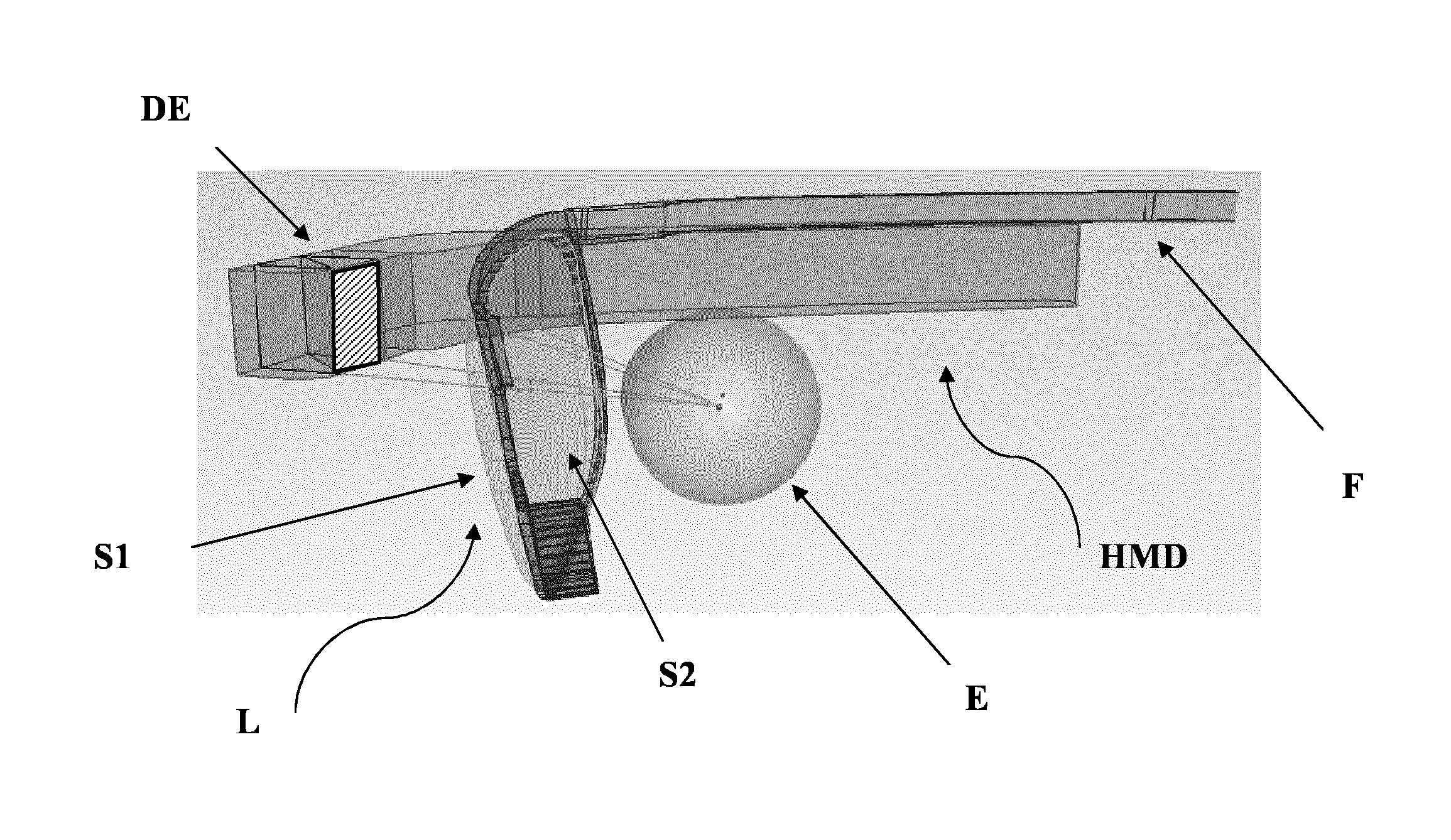
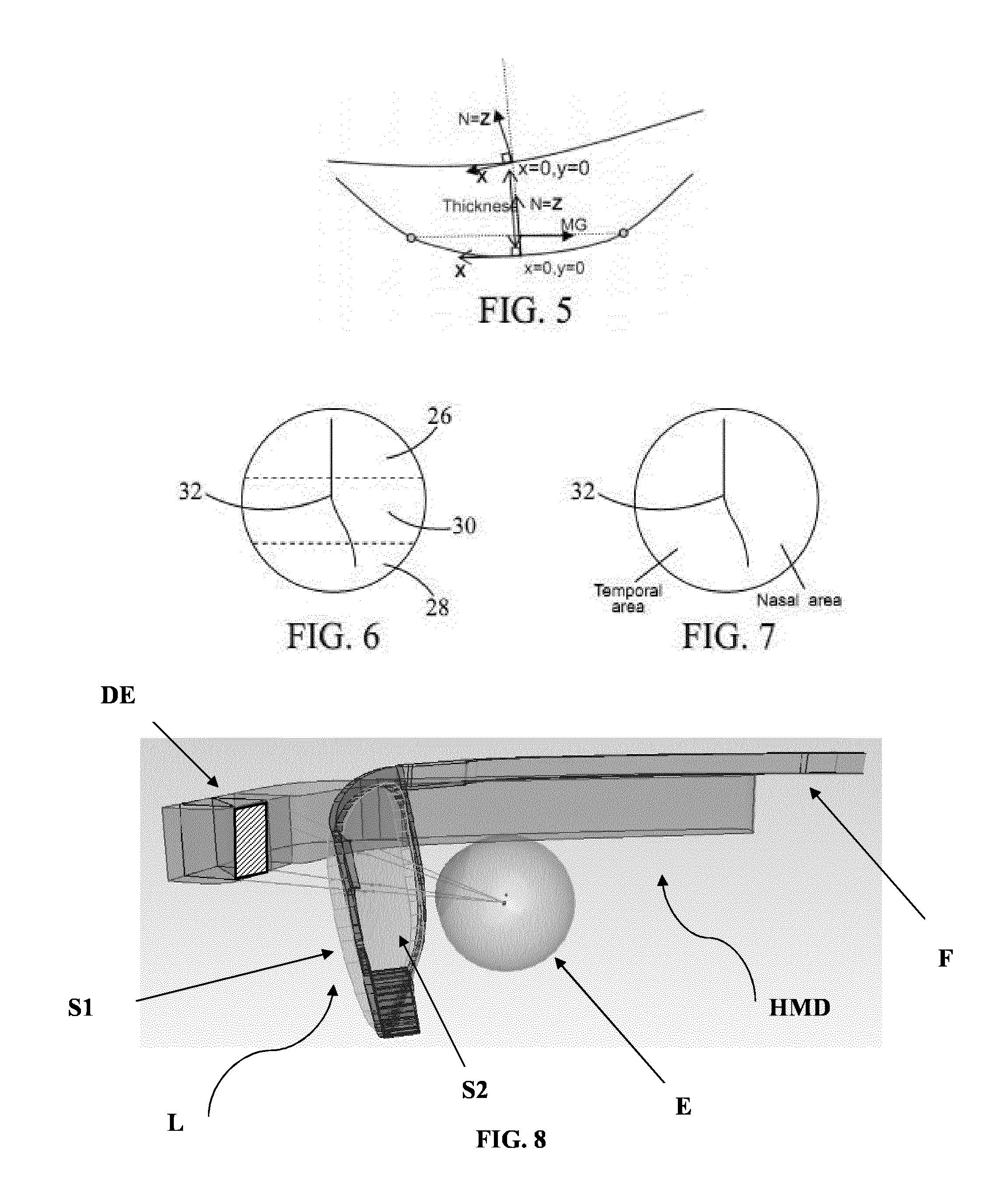
[0253]FIGS. 8-9 illustrate an exemplary HMD. The HMD comprises a frame F and a display element DE. It also comprises a lens L with object-side surface S1 and eye-side surface S2. The figures show the relative position of the eye E, the lens L and the display element DE.
[0254]FIGS. 10 and 11a-11b illustrate two different configurations for the HMD. The distance between the HMD and the eye is shorter in the HMD of FIG. 10 than on that of FIG. 11a. Dashed lines show possible ray tracing for the determination of the zone of stabilized optical performance (virtual vision, stabilized optical properties). FIGS. 11b and 12 show sub-parts SP1, SP2.
example 2
Lenses
[0255]Lenses are designed for the following prescription values (P, Asti)=(6.00, 0.00), The following methods are implemented for lens design:[0256]no optimization (NO OPTIM);[0257]first method with target-mediated optical optimization (OPTIM1);[0258]second method with target-mediated optical optimization (OPTIM2);[0259]third method with surface combination (OPTIM3).
[0260]No Optim[0261]rear lens surface is spherical and designed to reach desirable prescription at optical center of the lens;[0262]the lens is analyzed in wearing condition[0263]the area of lens useful for virtual vision (zone of stabilized optical performance) has optical power and astigmatism defects of more than 0.5 D;[0264]at the optical center of the lens, there are also defects of optical power (0.06 D) and astigmatism (0.19 D).
[0265]Results are shown on FIG. 14.
[0266]OPTIM1[0267]lens is optimized in the desired areas, using target definition;[0268]optimization is carried out by ray tracing (wrap angle 7°, p...
example 3
Single Vision Lenses
[0281]Further lenses according to the invention are exemplified (FIGS. 30-38).
[0282]All results of Example 2 and 3 show that one or more of the following criteria C1; C2; C3 are met according to the invention:[0283]C1: The zone of stabilized optical performance (SP1, SP2) is arranged so that:[0284]said second sub-part (SP2) can be inscribed within a square of the eye-side surface (S2) having a length of side of 12-30° when measured as a distance in said (α,β) coordinates, with a, β expressed in degrees (°);[0285]said second sub-part (SP2) comprises a geometrical barycenter located on the eye-side surface (S2) of the lens in a location of the eye-side surface (S2) in a peripheral vision gaze direction; wherein the peripheral vision zone is defined as the set of gaze directions (αi,βi), with αi, βi expressed in degrees (°), such that SQRT(αi2+βi2)≧150;[0286]it is stabilized in terms of optical power and / or unwanted astigmatism, so that over the entire zone, optical...
PUM
 Abstract
Description
Claims
Application Information
 - R&D
- Intellectual Property
- Life Sciences
- Materials
- Tech Scout
- Unparalleled Data Quality
- Higher Quality Content
- 60% Fewer Hallucinations
Browse by: Latest US Patents, China's latest patents, Technical Efficacy Thesaurus, Application Domain, Technology Topic, Popular Technical Reports.
© 2025 PatSnap. All rights reserved.Legal|Privacy policy|Modern Slavery Act Transparency Statement|Sitemap|About US| Contact US: help@patsnap.com


