Ultrasound imaging pickup apparatus

a pickup apparatus and ultrasonic technology, applied in the direction of tomography, instruments, applications, etc., can solve the problems of difficult to improve the resolution in the direction of an azimuthal angle, and the inability to prepare arrays of infinite length, so as to achieve the effect of deteriorating image quality in the vicinity of the depth of the transmit focus

Active Publication Date: 2017-02-16
FUJIFILM HEALTHCARE CORP
View PDF0 Cites 6 Cited by
  • Summary
  • Abstract
  • Description
  • Claims
  • Application Information

AI Technical Summary

Benefits of technology

[0011]The focusing-type transmission method has smaller errors between delay times even in the case where the divergence angle of transmission is large in comparison with the dispersing-type transmission method. Therefore, in the focusing-type transmission method, because the divergence angle of the transmitted ultrasound wave can be set large, a larger number of reception scanning lines (assemblies of points at which phased signals are calculated) can be set in comparison with in the dispersion-type transmission method. It becomes possible to speedily image a wider imaged area with a fewer number of transmissions by setting a many number of reception scanning lines. In addition, in transmission aperture processing, more phased signals can be synthesized in the case of a large number of reception scanning lines being set than in the case of a small number of reception scanning lines being set even if the same number of transmissions are executed in both cases, and advantageous effects such as the improvement of resolution can be obtained.
[0012]Furthermore, as shown in Patent Literature 2, delay times are calculated in the irradiation area of a transmission beam (in an area where ultrasound energy is converged) using the virtual source method, and delay times are calculated under the assumption that a spherical wave is irradiated from the end of a probe outside of the irradiation area of the transmission beam areas where the energy of the ultrasound beam disperses), which makes it possible to obtain phased signals even at points outside of the irradiation area of the transmission beam. Therefore, reception scanning lines can be set even outside of the irradiation area of the transmission beam.
[0013]However, in the case where delay times at points on a reception scanning line outside of the irradiation area of the transmission beam are calculated using the waveform of a spherical wave which is considered to be irradiated from the end of the probe according to the technology disclosed in Patent Literature 2, the waveform of the spherical wave used for calculation of the delay times have to be switched from the waveform f a spherical wave irradiated from the left part of the edge of the probe to the waveform of a spherical wave irradiated from the right part of the edge of the probe or vice versa in the vicinity of the depth of a transmit focus. Owing to this switching, there arises a problem in that a curve representing the variation between delay times in the direction of the depth along the reception scanning line becomes discontinuous in the vicinity of the depth of the transmit focus. Unless the discontinuity of the variation between the delay times in the vicinity of the depth of the transmit focus is approximated by some kind of approximating curve or another to change the discontinuous curve into a continuous curve, the pixel values of an ultrasound image to be generated become discontinuous in the vicinity of the depth of the transmit focus, so that an artifact is generated. In this case, such an approximating curve has to have a complex shape including one or more inflection points to continuously connect the discontinuous variation between the delay times.
[0014]On the other hand, because a typical ultrasound image pickup apparatus has a limited calculation capacity, delay times regarding all reception phasing points (sampling points at the time of phasing of reception signals) on the reception scanning line cannot be calculated using the virtual source method or using the waveform of a spherical wave. Therefore, after setting segments whose lengths are longer than the distance between the reception phasing points on the reception scanning line, delay times are calculated regarding only nodes between the segments using the virtual source method or using the waveform of a spherical wave. Next, delay times regarding reception phasing points within a segment are calculated using linear interpolation calculation or the like with reference to delay times at the nodes of the both ends of the segment. Herewith, the calculation amount of delay times can be controlled, and the high-speed display of the ultrasound images can be realized.
[0015]Therefore, in the case where delay times at reception phasing′ points in the vicinity of the depth of a transmit focus are intended to be calculated using the technology disclosed in the abovementioned Patent Literature 2, if distances between segments are large, it is impossible to set delay times, in which the change of the abovementioned approximating curve is reflected, at the reception phasing points using interpolation calculation. In addition, although the shape of the curve of delay times at reception phasing points complexly varies depending on a transmission condition and the position of a reception scanning line, if the lengths of segments are large, the interpolation calculation cannot cope with the change of the shape of the curve of the delay times. Therefore, image qualities in the vicinity of the depth of the transmit focus become deteriorated.
[0016]One of the objects of the present invention is to execute reception beamforming using delay times that complexly vary depending on differences between transmission conditions.

Problems solved by technology

Because the transmission or reception of ultrasound waves by an ultrasound image pickup apparatus is performed by means of an array with an aperture of a finite diameter, the transmission or reception is affected by the diffractions of the ultrasound waves caused by the edge of the aperture, therefore it is difficult to improve the resolution in the direction of an azimuthal angle.
The above problem can be solved if an array of an infinite length can be prepared, but in actuality it is impossible to prepare an array of an infinite length.

Method used


Image

  • Ultrasound imaging pickup apparatus
  • Ultrasound imaging pickup apparatus
  • Ultrasound imaging pickup apparatus

Examples


first embodiment

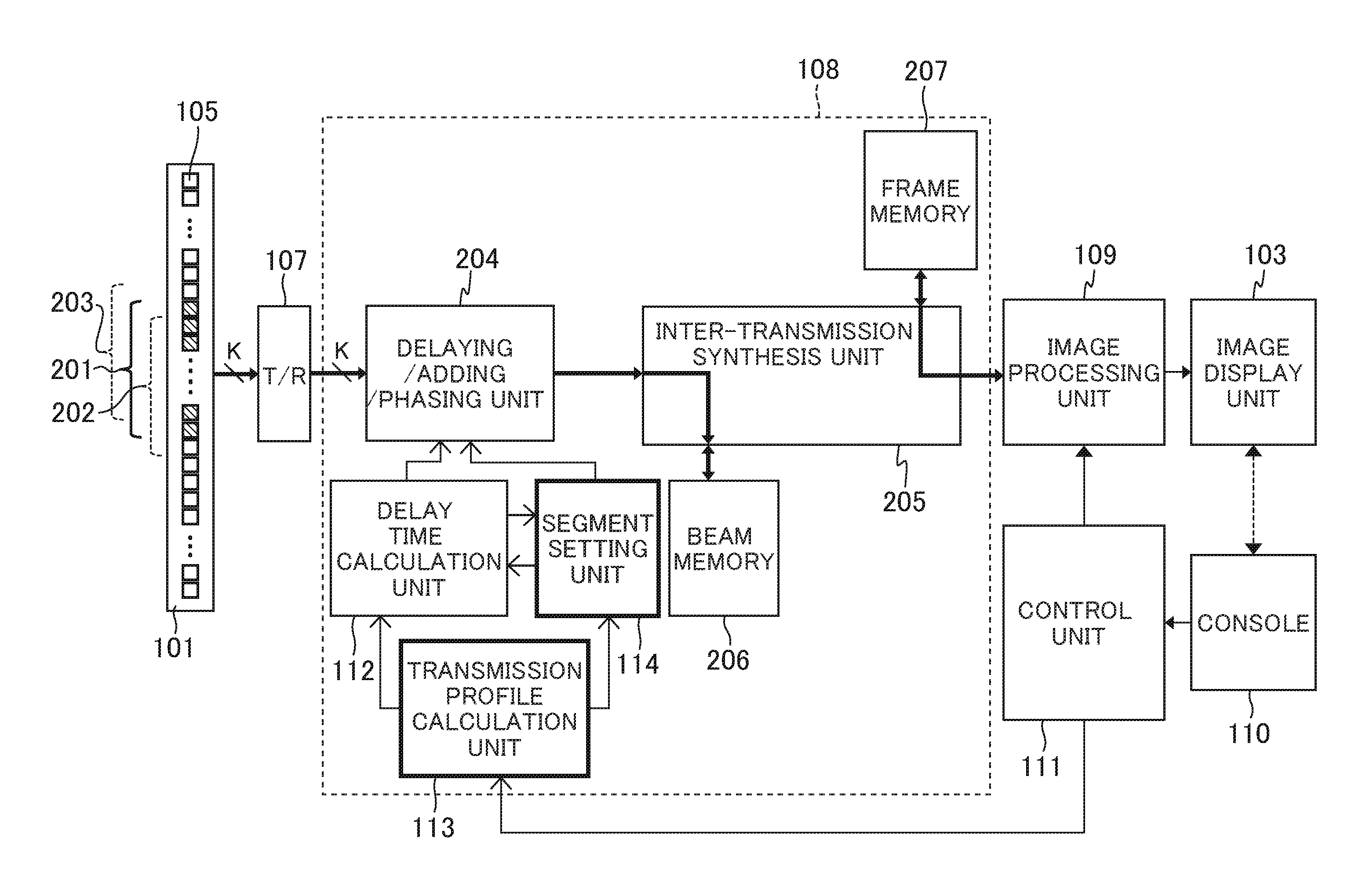
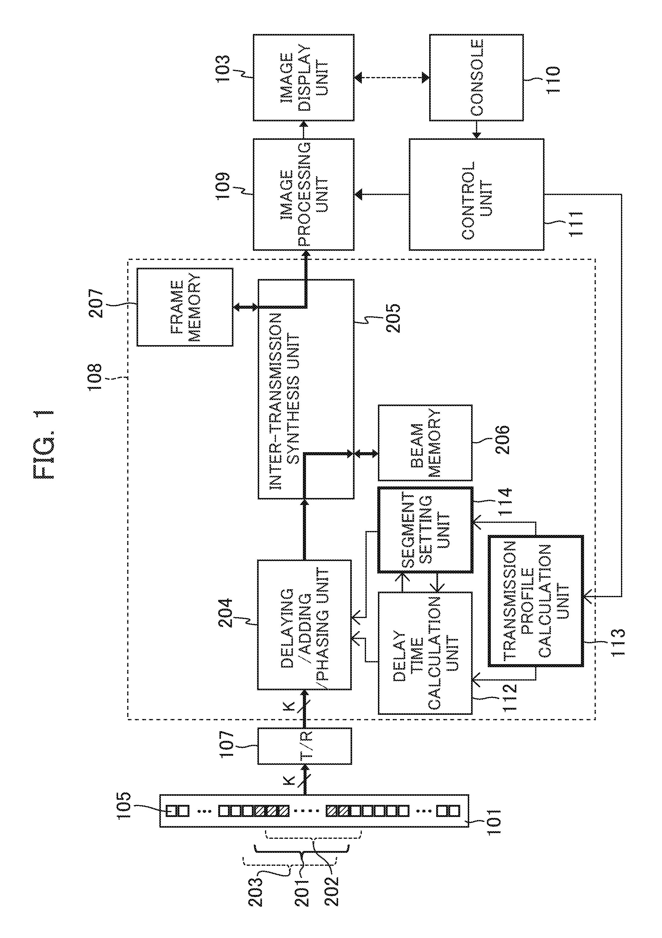
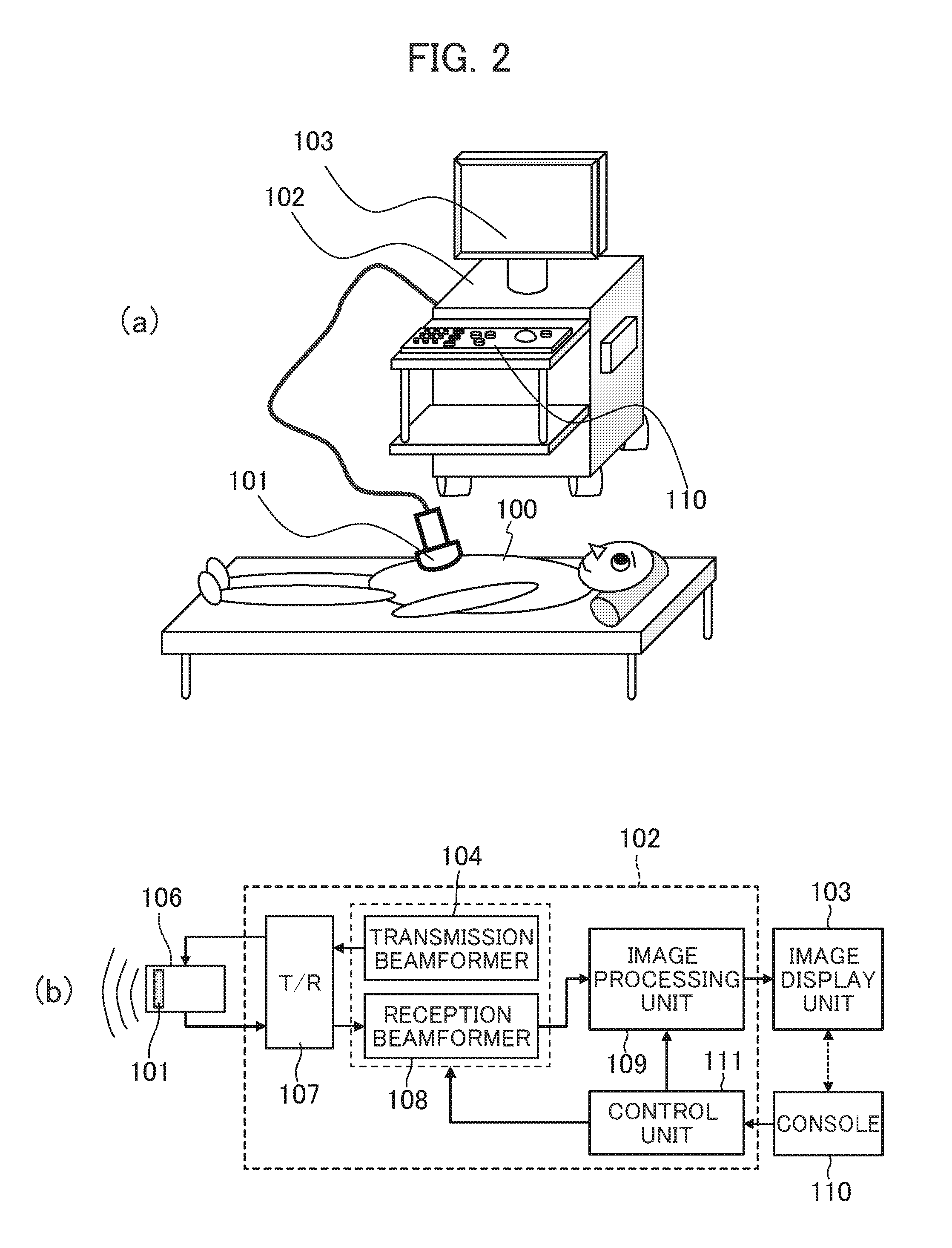
[0035]An ultrasound image pickup apparatus of a first embodiment will be explained with reference to FIG. 1, FIGS. 2(a) and (b). FIG. 1 is a block diagram showing a part of the apparatus, FIG. 2(a) is a perspective view of the apparatus, and FIG. 2(b) is a block diagram showing the schematic configuration of the entirety of the apparatus.

[0036]As shown in FIG. 1, FIGS. 2(a) and (b), the ultrasound image pickup apparatus of the first embodiment includes: an ultrasound element array 101 in which plural ultrasound elements 105 are arranged in a predefined direction; a transmission beamformer 104 that makes at least a part (201, 202, and 203) of the plural ultrasound elements 105 transmit a focusing-type transmission beam to the imaged area of a test object 100; a reception beamformer 108 that delays reception signals output by the plural of ultrasound elements 105, which receive ultrasound waves from the test object 100, by delay times to phase the reception signals, and adds the phase...

second embodiment

[0080]An ultrasound image pickup apparatus of a second embodiment will be explained below.

[0081]In the second embodiment, a segment setting unit 114 makes a delay time calculation unit 112 calculate a delay time for each reception phasing point 5 in an outer area B located outside of an irradiation area 32 among reception scanning lines 31. Subsequently, a curve showing the relationship between the delay times obtained by the calculation and the positions of the reception phasing points 5 is calculated. The segment length of a segment in an area where the change (gradient) of the curve is large is set short, while the segment length of a segment in an area where the change (gradient) of the curve is small is set long.

[0082]The above procedure will be concretely explained with reference to FIG. 10. A transmission profile calculation unit 113 and the segment setting unit 114 calculates intersection points 34 between a transmission profile 32 and the reception scanning lines 31 as is t...

third embodiment

[0089]An ultrasound image pickup apparatus of a third embodiment will be explained below.

[0090]In the third embodiment, a segment setting unit 114 makes a delay time calculation unit 112 calculate a delay time for each reception phasing point in an outer area B located outside of an irradiation area 32 among reception scanning lines 31. The segment setting unit 114 calculates a curve 131 showing the relationship between the obtained delay times and the positions of reception phasing points 5, and sets the nodes 4b of plural segments on the curve 131. Next, the segment setting unit 114 calculates plural line segments 132 that connect the set segment nodes 4b with straight lines. Next, the segment setting unit 114 calculates the dimensions of areas bounded by the curve 131 and the line segments 132, and adjusts the position of each of the nodes 4b of the plural segments (the segment length of each of the plural segments) respectively so that these dimensions become small.

[0091]The abo...


PUM


Abstract

Reception beamforming is executed using delay times that complexly vary in accordance with differences between transmission conditions. An irradiation area 32 of a transmission beam is calculated, and the lengths of segments, using which delay times are calculated, are set in accordance with the positional relationships between the calculated irradiation area 32 and reception scanning lines 31. For example, the reception scanning lines 31 are divided into areas A to C, and the lengths of segments 40b in the outer area B located outside of the irradiation area 32 are set shorter than the lengths of segments 40a and 40c in the inner areas A and C.

Description

TECHNICAL FIELD[0001]The present invention relates to an ultrasound imaging technology that takes images inside of a test object using ultrasound waves.BACKGROUND ART[0002]The ultrasound imaging technology is a technology that takes images of the inside of a test object such as a human body noninvasively using ultrasound waves (inaudible sound waves, that is, sound waves whose frequencies are typically 20 kHz or higher).[0003]As a transmission method for transmitting an ultrasound beam from an ultrasound probe to a test object such as a human body, there are two kinds of transmission methods; one is a dispersing-type transmission method in which an ultrasound beam that disperses in a fan shape is transmitted, and the other is a focusing-type transmission method in which the transmit focus of an ultrasound beam is disposed inside of a test object, and the ultrasound beam is converged on the focus.[0004]Because the transmission or reception of ultrasound waves by an ultrasound image p...

Claims


Application Information

Patent Timeline
Patent Type & Authority Applications(United States)
IPC IPC(8): A61B8/00A61B8/14
CPCA61B8/4488A61B8/5269A61B8/14A61B8/145A61B8/5207G01S7/5205G01S7/52085G01S15/8915G01S15/8997G10K11/346G01N29/262
Inventor IKEDA, TEIICHIROTAKANO, SHINTAMASUZAWA, HIROSHIISHIHARA, CHIZUESUZUKI, MAYUMI
Owner FUJIFILM HEALTHCARE CORP
Why Eureka
Try Eureka