Lens module

Active Publication Date: 2016-07-21
HIMAX TECH LTD
View PDF3 Cites 0 Cited by
  • Summary
  • Abstract
  • Description
  • Claims
  • Application Information

AI Technical Summary

Benefits of technology

[0006]One embodiment of the present invention provides a lens module with plural wafer level lens groups integrally formed. The wafer level lens groups are used for obtaining the image depth. The distance between the wafer level lens groups are determined in the wafer

Problems solved by technology

However, the present positioning method, such as surface-mount technolo

Method used


Image

  • Lens module
  • Lens module
  • Lens module

Examples


Example

[0015]Reference will now be made in detail to the present embodiments of the invention, examples of which are illustrated in the accompanying drawings. Wherever possible, the same reference numbers are used in the drawings and the description to refer to the same or like parts.

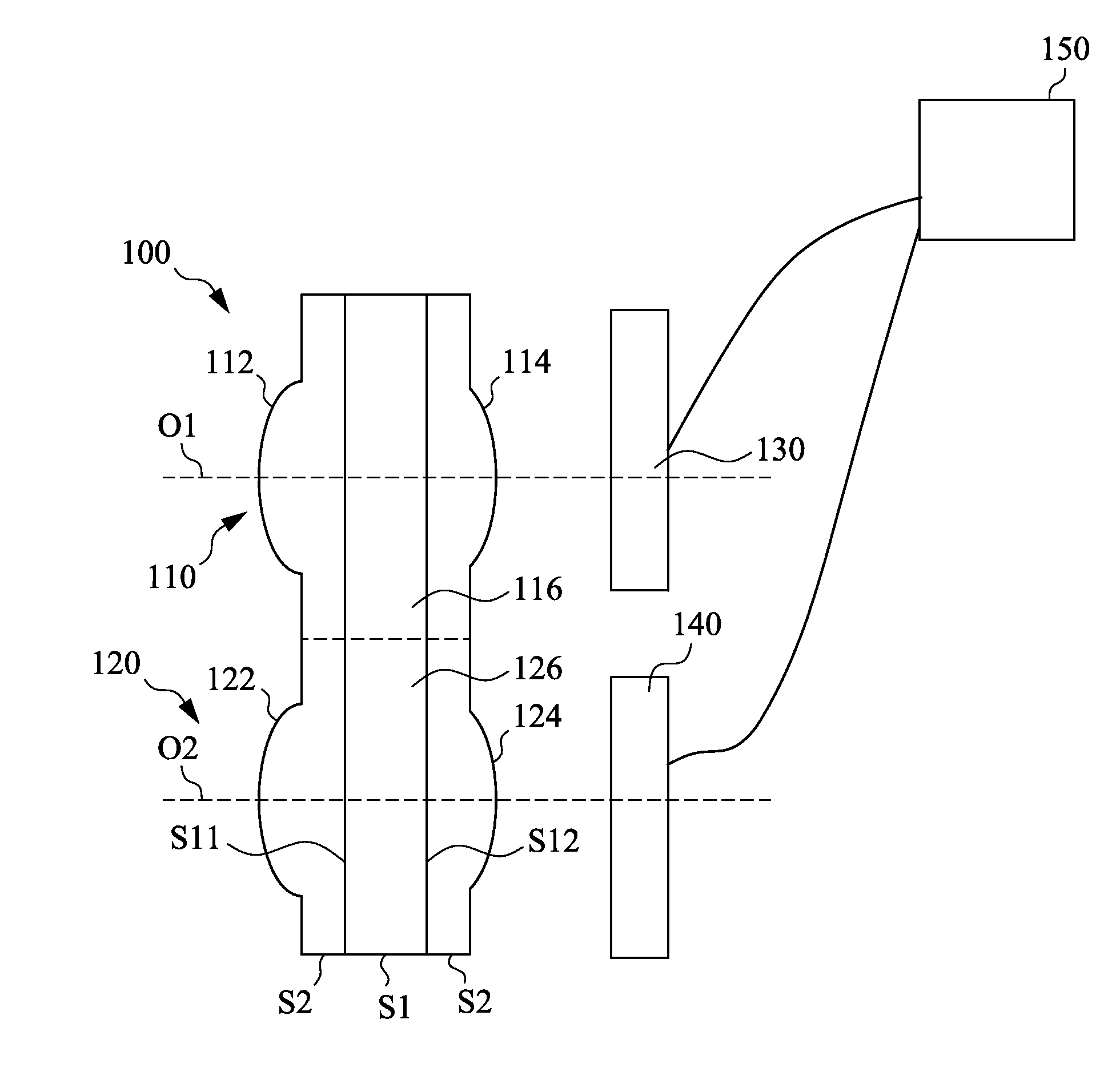
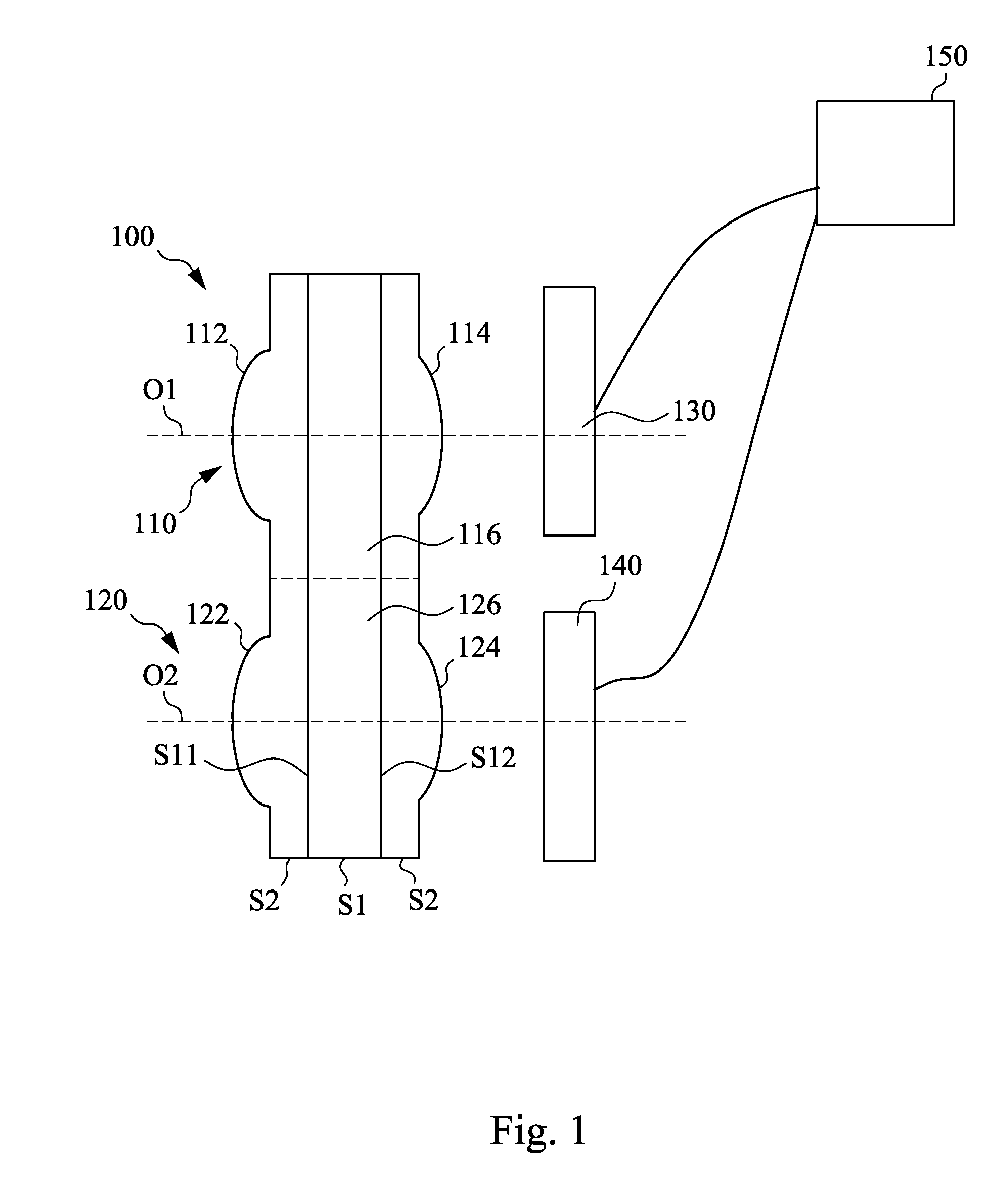
[0016]FIG. 1 is a cross-sectional view of a lens module 100 according to an embodiment of the invention. The lens module 100 includes a first wafer level lens group 110, a second wafer level lens group 120, a first sensor 130, and a second sensor 140. The first wafer level lens group 110 has a first optical axis O1. The second wafer level lens group 120 has a second optical axis O2. The first optical axis O1 is parallel with the second optical axis O2, and the first wafer level lens group 110 and the second wafer level lens group 120 are integrally formed. The first sensor 130 is disposed corresponding to the first wafer level lens group 110, and the first sensor 130 is disposed on the first optical axis O1. T...


PUM


Abstract

A lens module includes a first wafer level lens group, a second wafer level lens group, a first sensor, and a second sensor. The first wafer level lens group has a first optical axis. The second wafer level lens group has a second optical axis. The first optical axis is parallel with the second optical axis, and the first wafer level lens group and the second wafer level lens group are integrally formed. The first sensor is disposed corresponding to the first wafer level lens group, and the first sensor is disposed on the first optical axis. The second sensor is disposed corresponding to the second wafer level lens group, and the second sensor is disposed on the second optical axis.

Description

BACKGROUND[0001]1. Field of Invention[0002]The present invention relates to a lens module.[0003]2. Description of Related Art[0004]Recently, many scene-detection systems attempt to extract depth from a scene by mimicking the human stereo perception system to produce two or more images. The scene-detection systems are applicable to cameras, smart phones, etc. In order for these scene-detection systems to operate properly, the scene-detection systems can be designed to receive two images from two separate but interconnected aspects, and then the images can be analyzed to obtain the depth.[0005]In the assembly of the scene-detection systems, to reach the above purposes, it is necessary to position optical elements of the scene-detection systems accurately since the depth analyzation is performed based on the distance between the optical elements. However, the present positioning method, such as surface-mount technology, cannot control the distance between the optical elements accuratel...

Claims


Application Information

Patent Timeline
IPC IPC(8): H04N13/02G02B13/00H04N13/239
CPCH04N13/0239G02B13/0025G02B13/006G02B13/0085H04N13/239H04N23/45H04N23/57
Inventor LU, YIN-DONGKUO, HAN-YI
Owner HIMAX TECH LTD
Why Eureka
Try Eureka