A Test Method of Amplitude and Phase of tr Module Based on Matrix Gating

An amplitude and phase testing and component technology is applied in the field of testing the amplitude and phase of active phased array radar TR components. Simple and convenient, the effect of increasing equipment cost

Active Publication Date: 2018-09-25
LINGBAYI ELECTRONICS GRP
View PDF3 Cites 0 Cited by
  • Summary
  • Abstract
  • Description
  • Claims
  • Application Information

AI Technical Summary

Problems solved by technology

This method has very strict requirements on the relative position of the auxiliary antenna and the antenna under test (related to the wavelength), and is suitable for the detection and calibration of fixed-installed phased array radars, but not applicable to vehicle-mounted phased array radars. The environment is good, otherwise the test will be affected
Orthogonal feeding method adopts the antenna internal power division network to couple the test signal to all the units under test at the same time. The test signal adopts the orthogonal coding waveform, and the signal processing is through the multiplication and addition operation of the test signal to separate and calculate the amplitude and phase information of each unit under test. , although this method does not connect external equipment, the signal generation and processing are complicated, and when the number of faulty units is large, the test accuracy is greatly reduced, and even has no reference significance

Method used


Image

  • A Test Method of Amplitude and Phase of tr Module Based on Matrix Gating
  • A Test Method of Amplitude and Phase of tr Module Based on Matrix Gating
  • A Test Method of Amplitude and Phase of tr Module Based on Matrix Gating

Examples


Embodiment Construction

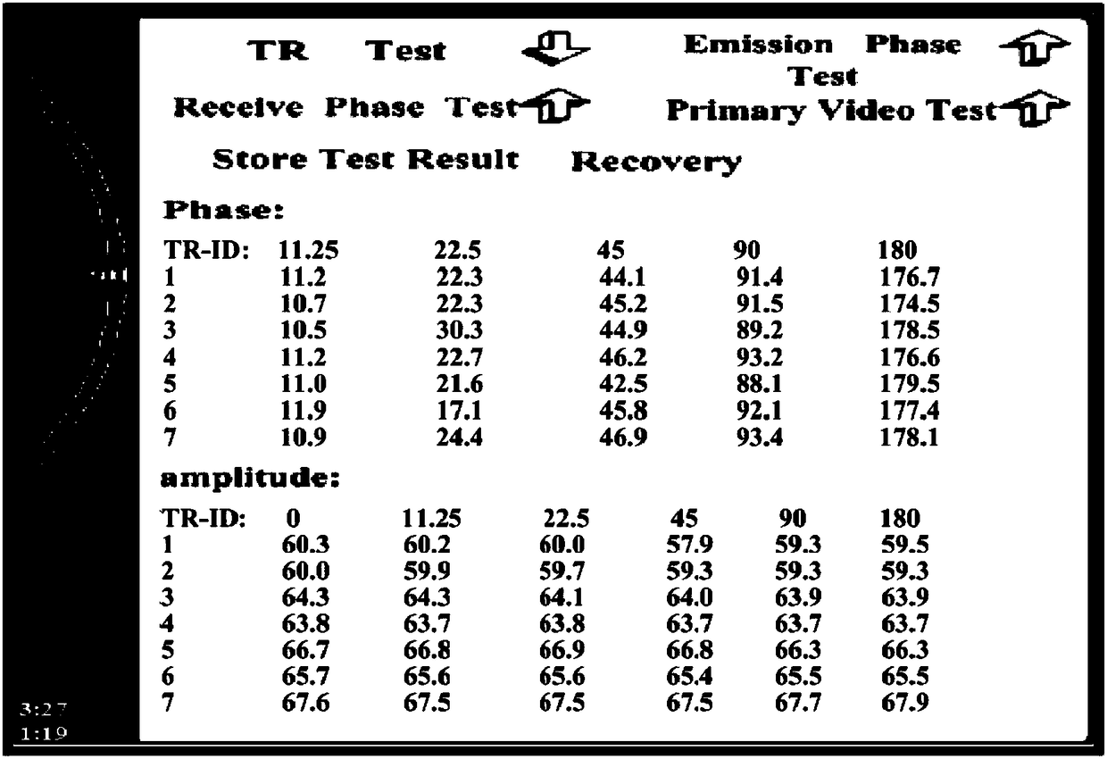
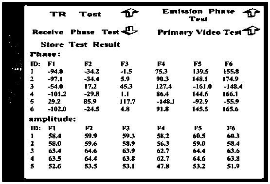
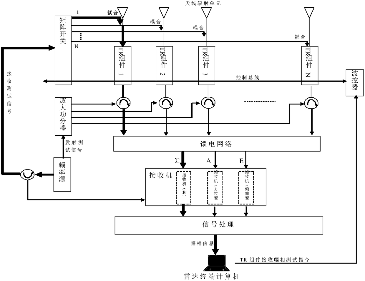
[0019] refer to figure 1 . According to the present invention, a multi-channel matrix switch is additionally installed in the phased array radar antenna. Then the test signal is generated by the internal frequency source of the radar, and the test signal is sent to the input terminal of the matrix switch. Controlled by the wave control, the phase shift, amplitude modulation and frequency conversion are carried out step by step according to the program. The amplitude phase adjustment and frequency conversion information is superimposed on the test signal, and the test signal with the information of the unit under test is superimposed and sent to the receiver connected to it. The machine converts the input signal down and amplifies it and sends it to the signal processor connected to it. The signal processor calculates the measured amplitude and phase information carried on the test signal through digital signal processing, and the information is finally sent to the radar term...


PUM


Abstract

The invention discloses a method for testing the amplitude and phase of a TR module based on matrix gating. According to the invention, the method can noticeably reduce workload of test workers. The method is implemented by the following technical solutions: mounting a multipath matrix switch on a phased array radar antenna for receiving test signals, a frequency source inside a radar generating two paths of test signals, inputting a to-be-tested TR module and a feed branch through the matrix switch; a wave controller, according to a TR module receiving amplitude and phase testing command program by a radar terminal computer, superimposing amplitude and phase adjustment and frequency conversion information on the test signals, transmitting the test signals superimposed with the amplitude and phase information to a receiver connected thereto, the receiver transmitting the input signals to a signal processor connected thereto after conducting down-conversion and amplification on the input signals, the signal processor computing the amplitude values and the phase values of the test signals, the radar terminal computer comparing the actual amplitude values and the actual phase values with the theoretic amplitude value and the theoretic phase value, and determining whether the TR module and the feed branch are normal so as to acquire the phase shift and amplitude modulation error of the TR module. The aforementioned steps are continued until the completion of the testing of all TR assemblies and corresponding feed networks.

Description

technical field [0001] The invention relates to a method for testing the amplitude and phase of a TR component of an active phased array radar, in particular to a method for testing the key equipment in the phased array—the TR component and its related feeding network. Background technique [0002] The TR component is the core component of the phased array radar active distributed array antenna, and its performance directly determines the performance of the entire radar system. A phased array radar usually has hundreds or even thousands of TR components, and it takes a long time to manually test or calibrate TR components. In the development and production process of phased array radar, the automatic test technology of TR components and active phased array is one of the key technologies that affect the product development and production progress and product quality. Since the performance of the phased array antenna is closely related to the consistency of the amplitude and ...

Claims


Application Information

Patent Timeline
Patent Type & Authority Patents(China)
IPC IPC(8): G01S7/40
CPCG01S7/4004
Inventor 谭博张杰张静张文宝伍怀琪张绍华延伟勤
Owner LINGBAYI ELECTRONICS GRP
Why Eureka
Try Eureka