

Squirrel-cage motor rotor and squirrel-cage motor
a squirrel-cage motor and rotor technology, applied in the direction of dynamo-electric machines, electrical apparatus, magnetic circuit shapes/forms/construction, etc., can solve the problems of repeated stress on the short-circuit ring and metal fatigue, and achieve the prevention of short-circuit ring breakage due to metal fatigue, the effect of preventing the detachment or displacement of the reinforcement cover
- Summary
- Abstract
- Description
- Claims
- Application Information
AI Technical Summary
Benefits of technology
Problems solved by technology
Method used
Image

Examples
embodiment 1
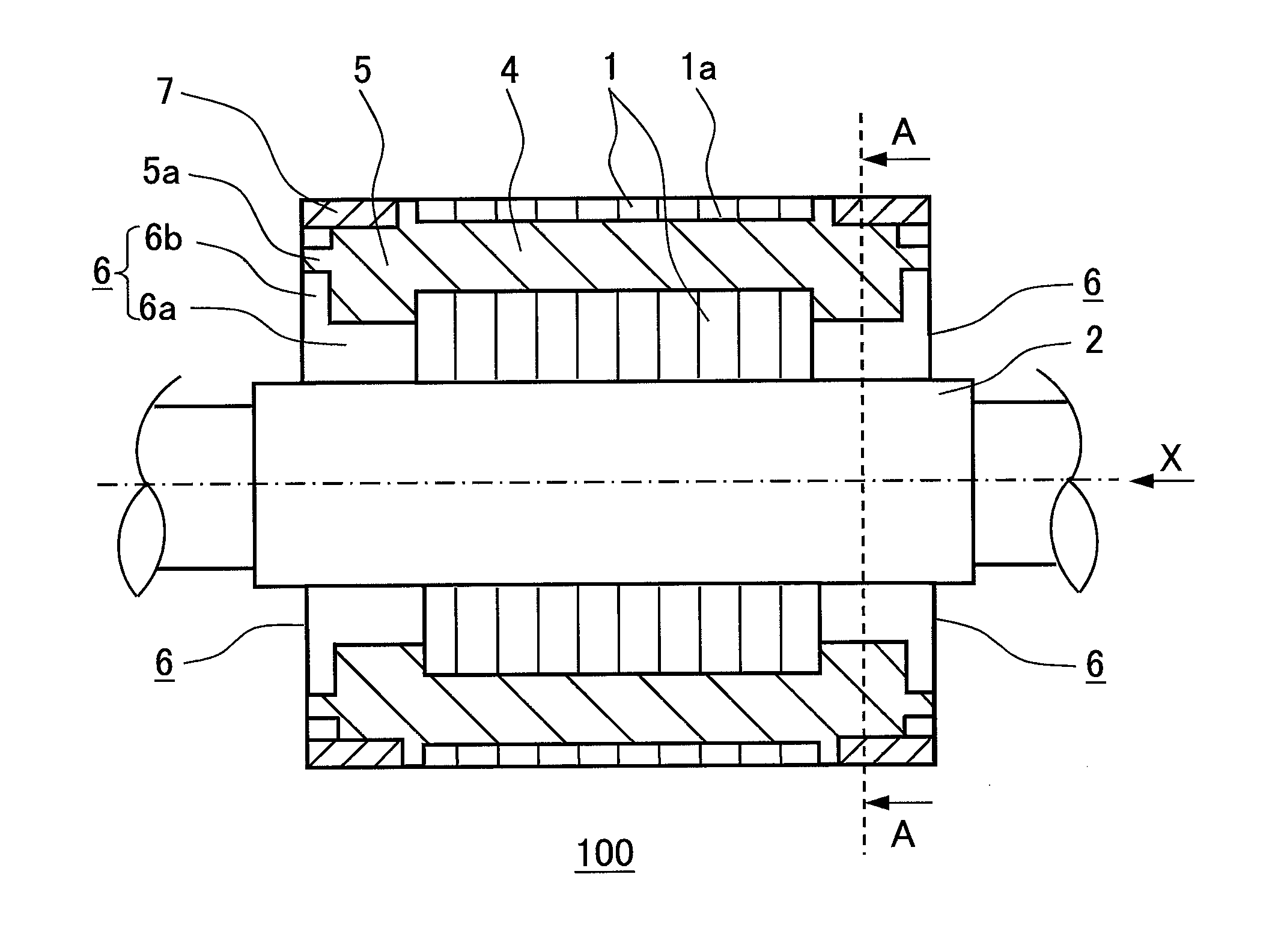
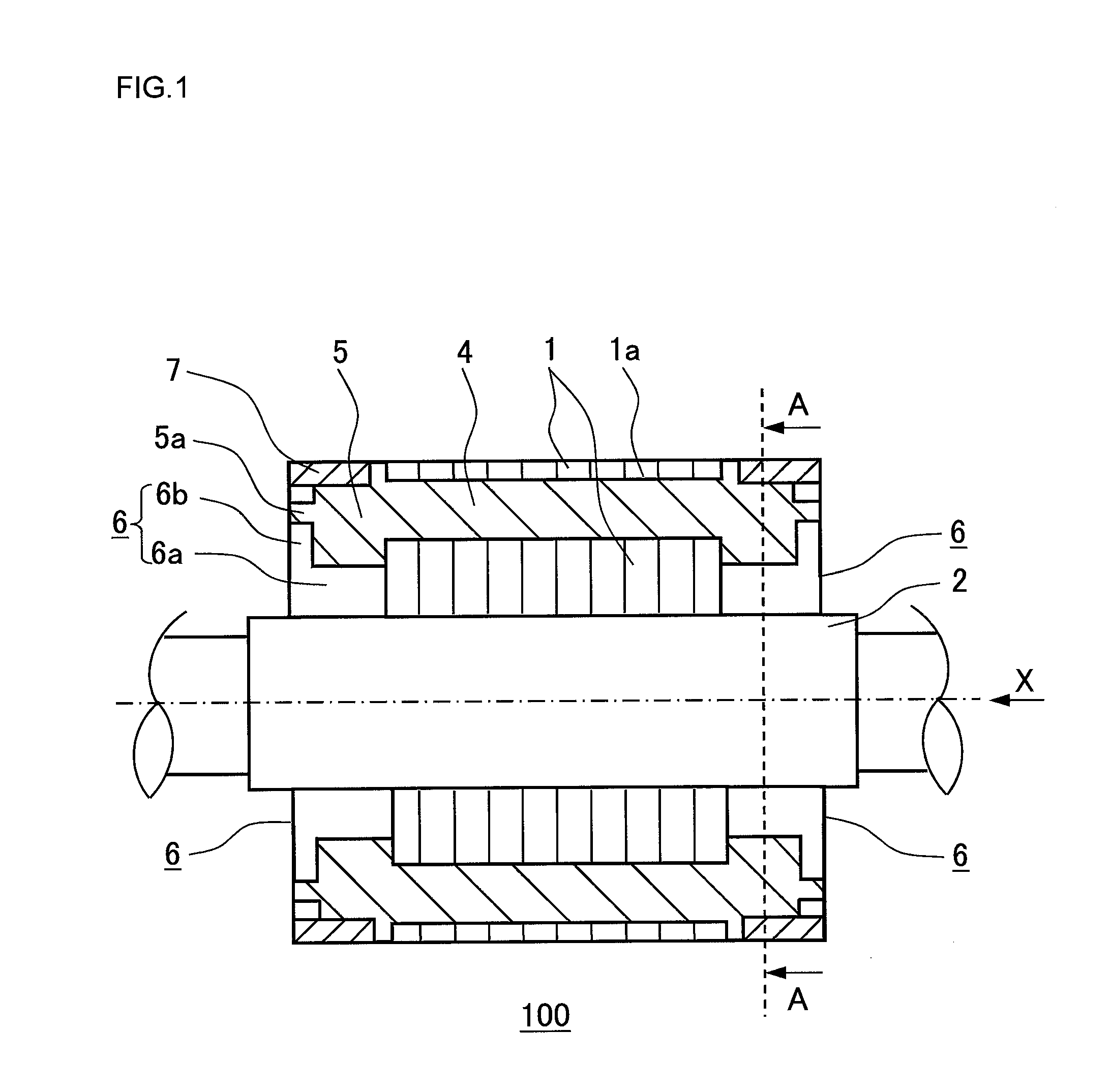
[0042]FIG. 1 is a schematic sectional view of a squirrel-cage motor rotor according to embodiment 1 of the present invention.
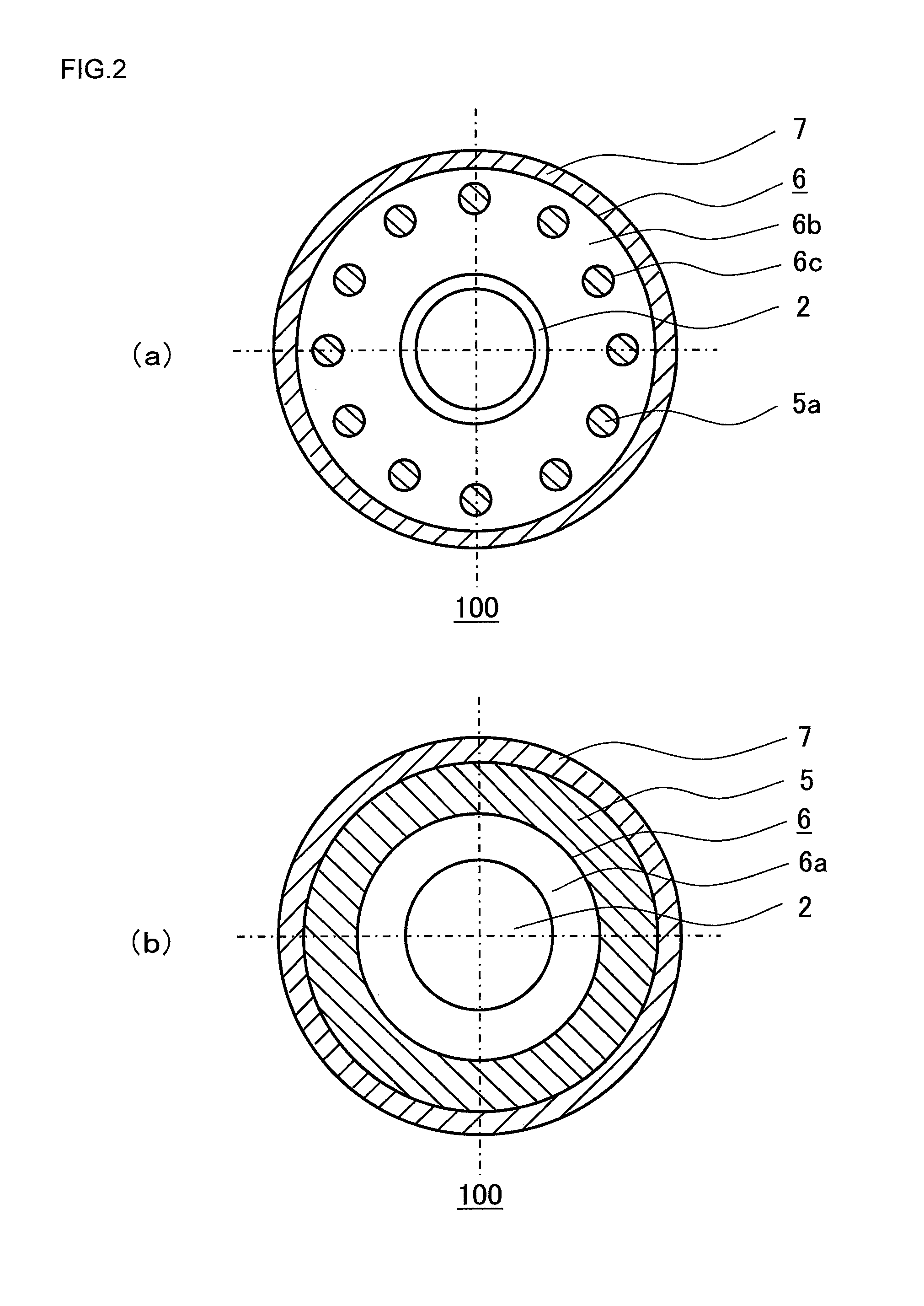
[0043]FIG. 2 is a schematic plan view (a) as seen from the direction indicated by an arrow X and a schematic view (b) of an A-A cross section, of the squirrel-cage motor rotor according to embodiment 1 of the present invention shown in FIG. 1.
[0044]FIG. 2 shows a plan view and a sectional view of the entirety of a squirrel-cage motor rotor 100 of the present embodiment.
[0045]As shown in FIG. 1 and FIG. 2, the squirrel-cage motor rotor 100 of the present embodiment includes a cylindrical rotor core 1 formed by stacking electromagnetic steel sheets, conductor bars 4 respectively filling a plurality of slot holes 1a which penetrate the rotor core 1 in the axial direction and are arranged at regular intervals along the circumferential direction of the rotor core 1, short-circuit rings 5 connected to ends of the conductor bars 4, reinforcement covers 6 contacting w...
embodiment 2
[0083]FIG. 5 is a schematic sectional view of a squirrel-cage motor rotor according to embodiment 2 of the present invention.
[0084]FIG. 6 is a schematic plan view (a) as seen from the direction indicated by an arrow X and a schematic view (b) of a B-B cross section, of the squirrel-cage motor rotor according to embodiment 2 of the present invention shown in FIG. 5.
[0085]FIG. 6 shows a plan view and a sectional view of the entirety of a squirrel-cage motor rotor 200 of the present embodiment.
[0086]As shown in FIG. 5 and FIG. 6, the squirrel-cage motor rotor 200 of the present embodiment includes a cylindrical rotor core 1 formed by stacking electromagnetic steel sheets, conductor bars 4 respectively filling a plurality of slot holes 1a which penetrate the rotor core 1 in the axial direction and are arranged at regular intervals along the circumferential direction of the rotor core 1, short-circuit rings 5 connected to ends of the conductor bars 4, reinforcement covers 26 contacting w...
embodiment 3
[0106]FIG. 7 is a schematic sectional view of a squirrel-cage motor rotor according to embodiment 3 of the present invention.
[0107]FIG. 8 is a schematic plan view (a) as seen from the direction indicated by an arrow X and a schematic view (b) of a C-C cross section, of the squirrel-cage motor rotor according to embodiment 3 of the present invention shown in FIG. 7.
[0108]FIG. 8 shows a plan view and a sectional view of the entirety of a squirrel-cage motor rotor 300 of the present embodiment.
[0109]As shown in FIG. 7 and FIG. 8, the squirrel-cage motor rotor 300 of the present embodiment includes a cylindrical rotor core 1 formed by stacking electromagnetic steel sheets, conductor bars 4 respectively filling a plurality of slot holes 1a which penetrate the rotor core 1 in the axial direction and are arranged at regular intervals along the circumferential direction of the rotor core 1, short-circuit rings 5 connected to ends of the conductor bars 4, reinforcement covers 36 contacting w...
PUM
 Abstract
Description
Claims
Application Information