

Zipper slider
A slider and zipper technology, which is applied in the field of zipper sliders, can solve the problems of increased manufacturing costs of zipper sliders, and achieve the effects of reducing manufacturing costs and preventing metal fatigue
- Summary
- Abstract
- Description
- Claims
- Application Information
AI Technical Summary
Problems solved by technology
Method used
Image

Examples
no. 1 Embodiment approach
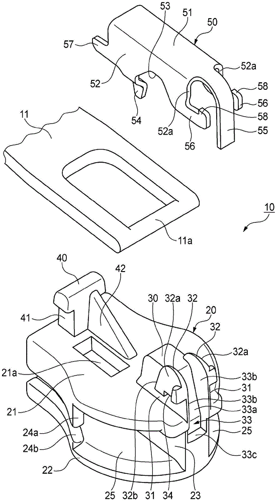
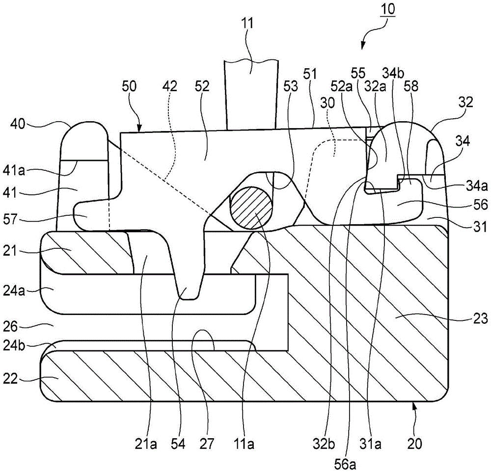
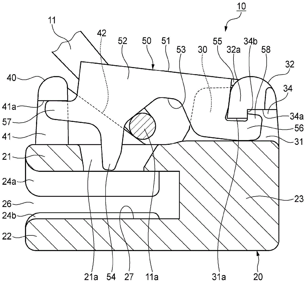
[0036] First, refer to Figure 1 to Figure 7 1st Embodiment of the slider for slide fasteners concerning this invention is demonstrated.
[0037] The slide fastener slider 10 of the present embodiment is a slider with an automatic stop function, such as figure 1 and figure 2 As shown, the slider 10 for a slide fastener has the main body 20 which has the element guide passage 27 which penetrates the main body 20 in the front-back direction inside. Specifically, the main body 20 includes: an upper wing 21 and a lower wing 22, which are separated in the vertical direction and arranged side by side; a guide column 23, which connects the front ends of the upper wing 21 and the lower wing 22; The flange 24a protrudes downward along the left and right edges of the upper wing 21 ; the lower flange 24b protrudes upward along the left and right edges of the lower wing 22 . Thereby, the left and right shoulder openings 25 separated by the guide posts 23 are formed at the front porti...
no. 2 Embodiment approach
[0055] Next, refer to Figure 8 ~ Figure 13 The second embodiment of the slide fastener slider of the present invention will be described. In addition, about the same or equivalent parts as those of the first embodiment, the same reference numerals as those of the first embodiment are attached in the drawings, and descriptions thereof are omitted or simplified.
[0056] In this embodiment, if Figure 8 , Figure 9 and Figure 11 As shown, instead of the locking step portion 34 and the locking protrusion 58 of the first embodiment described above, the upper wing plates 21 constituting the lower surfaces of the left and right front side engaged recesses 31 are respectively formed with downwardly recessed locking points. The step portion 61 is fixed, and locking protrusions 62 protruding downward and locking with the locking step portion 61 are respectively formed on the front end lower surfaces of the left and right paired front engaging pieces 56 .
[0057] On the left and ...
no. 3 Embodiment approach
[0065] Next, refer to Figure 14 ~ Figure 16 A third embodiment of the slide fastener slider of the present invention will be described.
[0066] The slide fastener slider 10 of the present embodiment is a slider with an automatic stop function, such as Figure 14 and Figure 15 As shown, the slider 10 for a slide fastener has the main body 20 which has the element guide passage 27 which penetrates the main body 20 in the front-back direction inside. Specifically, the main body 20 includes: an upper wing 21 and a lower wing 22, which are separated in the vertical direction and arranged side by side; a guide column 23, which connects the front ends of the upper wing 21 and the lower wing 22; The flange 24a protrudes downward along the left and right edges of the upper wing 21 ; the lower flange 24b protrudes upward along the left and right edges of the lower wing 22 . As a result, left and right shoulder openings 25 separated by guide posts 23 are formed at the front portion...
PUM
 Abstract
Description
Claims
Application Information