Al technical title is built by PatSnap Al team. It summarizes the technical point description of the patent document.
a technology of emergency notification and response system, applied in the field of security notification and communication, can solve problems such as problems for security personnel to assess and control situations, and achieve the effect of improving rain- or water-resistance and safe housing of components
Inactive Publication Date: 2017-03-09
JACOBS MICHAEL JAHANGIR
View PDF12 Cites 9 Cited by
Summary
Abstract
Description
Claims
Application Information
AI Technical Summary
This helps you quickly interpret patents by identifying the three key elements:
Problems solved by technology
Method used
Benefits of technology
[0011]The invention is based on the present inventor's recognition that a faster and more effective response by security guards, law enforcement or other authorities, collectively “security personnel” hereinafter, is possible by improving the communication of the condition of a room or building in an emergency situation. Certainly, the system and method may also be used during “non emergency” situations, such as drills, e.g., so-called “code red drills”.
[0072]The condition transmitter device according to the present invention provides improved communication in an emergency situation. The condition transmitter device may further be adapted according to one or more embodiments discussed in the preceding or following with reference to the other aspects of the present invention.
Problems solved by technology
Although the specific process to be followed during a lockdown depends on the guidelines as set out by the respective school district, it typically is problematic for security personnel to assess and control the situation.
Method used
Image
Click on the blue label to locate the original text in one second.
Reading with bidirectional positioning of images and text.
Examples
Embodiment Construction
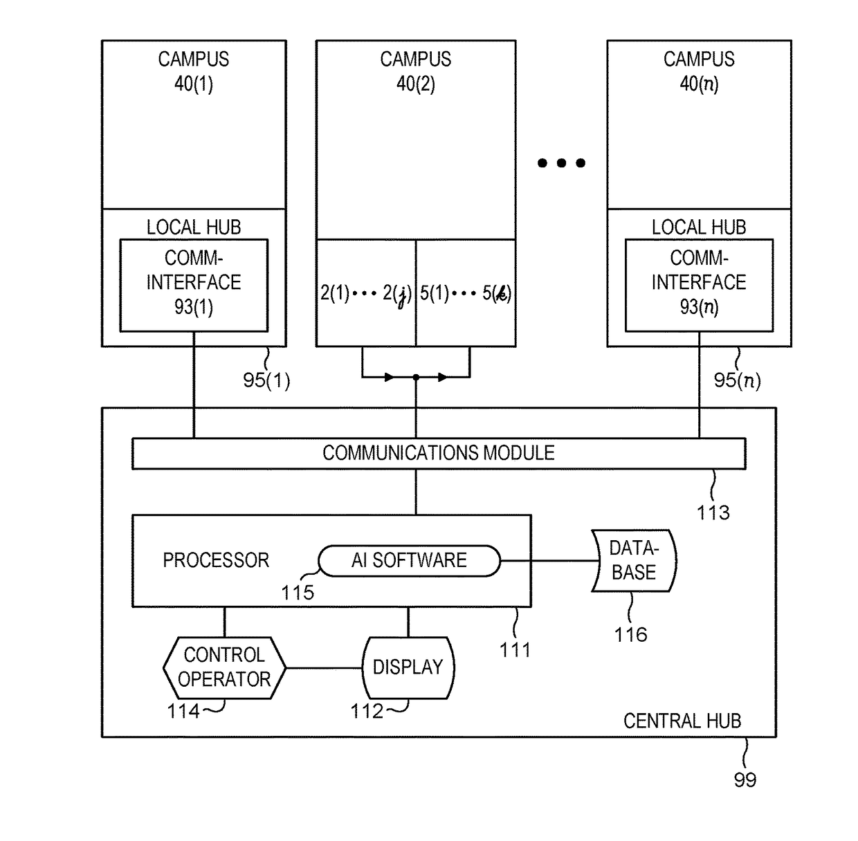
[0093]Technical features described in this application can be used to construct various embodiments of security condition notification systems and methods to facilitate response and assistance in an emergency situation.
[0094]It has been identified that in the field of security and safety and in particular during a so-called “lockdown” event in a private or public building 40, e.g., in a school, hospital or other private, public, or government building, it may be problematic for security personnel to assess and control the situation.
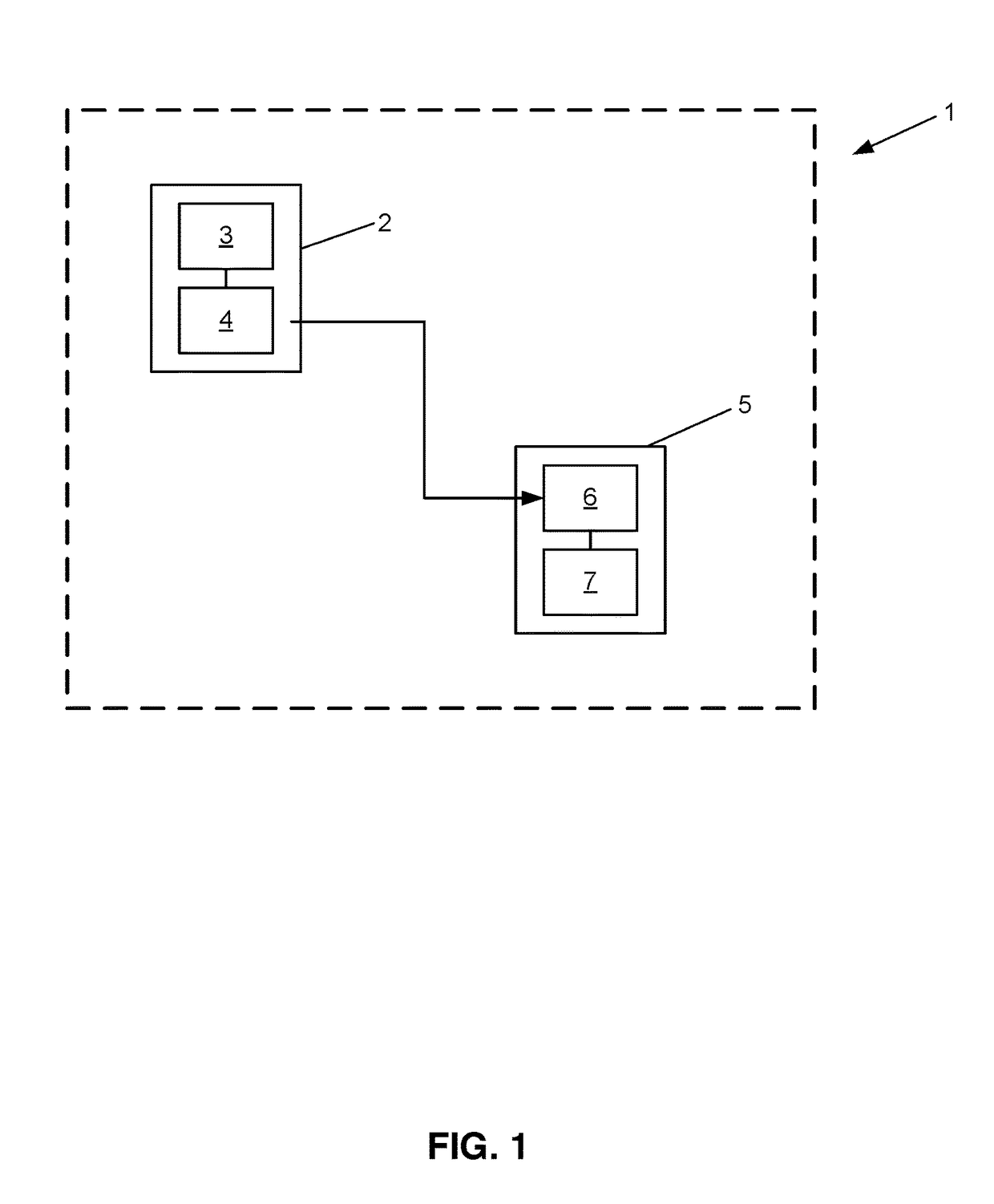
[0095]In one approach, the present inventor has recognized that a faster and more effective response by security guards, law enforcement or other authorities, collectively “security personnel” hereinafter, is possible by improving the communication of the condition of a room 41 or building 40 in an emergency situation.
[0096]By providing a security condition notification system as discussed in the following, communication is improved among those inside a r...
PUM
Abstract
A security condition notification system (1, 1′, 1″) providing improved communication for emergency situations. The system (1, 1′, 1″) comprises a condition transmitter device (2, 2′, 2″, 2′″) and a condition indicator device (5, 5′). The condition transmitter device (2, 2′, 2″, 2′″) comprises a user interface (3, 3′), configured to enable a user to activate one of at least a first and a second security condition. The condition transmitter device (2, 2′, 2″, 2′″) further comprises a transmitter communication interface (4, 4′) connected with said user interface (3, 3′) and configured for transmitting a security notification signal corresponding to the activated security condition to said condition indicator device (5, 5′). The condition indicator device (5, 5′) is configured to receive said security notification signal and comprises an indicator module (7,7′), configured to display the security condition of said condition transmitter device (2, 2′, 2″, 2′″), activated by the user. Local hubs (95) facilitate communications in multi-room (41) environments (40). A central hub (99) using artificial intelligence software (115) is present in some embodiments. A wearable device (100) having a mechanical vibrator (105) can be used as both a condition transmitter (2) and a condition indicator (5).
Description
RELATED PATENT APPLICATIONS[0001]This patent application is a continuation in part (CIP) of commonly-owned U.S. patent application Ser. No. 14 / 243,740 filed Apr. 2, 2014 entitled “Security Condition Notification System” (attorney docket MJAC 0396 US), which claims the priority benefit of commonly-owned U.S. provisional patent application 61 / 962,647 filed Nov. 12, 2013, entitled “Safeschoolz notifier system” (attorney docket MJAC 0396 PR); the contents of said two prior patent applications are hereby incorporated by reference in their entireties into the present patent application.TECHNICAL FIELD[0002]The present invention relates to the field of security, and in particular to security notification and communication, for example during a so-called “lockdown” event in a private or public building, e.g. in a school, hospital or other private, public, or government building.BACKGROUND ART[0003]In recent years, security protocols have been established to protect persons in public buildin...
Claims
Application Information
Patent Timeline
Application Date:The date an application was filed.
Publication Date:The date a patent or application was officially published.
First Publication Date:The earliest publication date of a patent with the same application number.
Issue Date:Publication date of the patent grant document.
PCT Entry Date:The Entry date of PCT National Phase.
Estimated Expiry Date:The statutory expiry date of a patent right according to the Patent Law, and it is the longest term of protection that the patent right can achieve without the termination of the patent right due to other reasons(Term extension factor has been taken into account ).
Invalid Date:Actual expiry date is based on effective date or publication date of legal transaction data of invalid patent.
Patent Type & Authority Applications(United States)